Selecting a Motor: Selection Example - Pulley Mechanism

For AC Motors

(1) Specifications and Operation Conditions of the Drive Mechanism

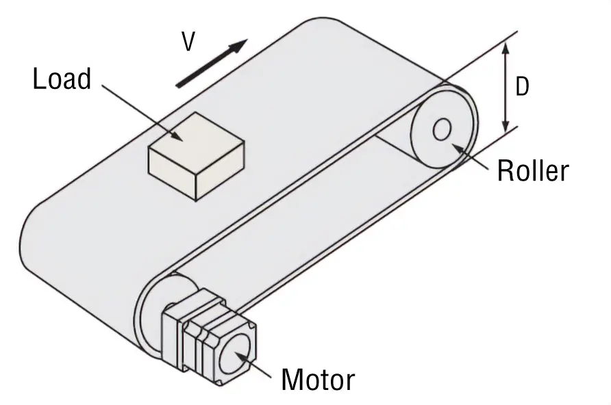
The following is an example of how to select an induction motor to drive a belt conveyor:
A motor must be selected that meets the following required specifications.

(1) Specifications and Operation Conditions of the Drive Mechanism
Total Mass of Belt and Load
m1 = 25 [kg]
External Force
F A = 0 [N]
Friction Coefficient of Sliding Surface
μ = 0.3
Roller Diameter
D = 90 [mm]
Roller Mass
m2 = 1 [kg]
Belt and Roller Efficiency
η = 0.9
Belt Speed
V = 180 [mm/s] ± 10 %
Motor Power Supply
Single-Phase 100 VAC 50 Hz
Operating Time
8 hours of operation per day

(2) Determine the Gear Ratio of Gearhead

\(\begin{align} \text{Gearhead Output Shaft Speed}\ N_G &=\frac{V \cdot 60}{\pi \cdot D} \\[5pt] &= \frac{(180 \pm 18) \times 60}{\pi \times 90}\\[ 5pt] &= 38.2 \pm 3.8\ [ \mathrm{r/min}]\end{align}\)

Since the rated speed for an induction motor (4-pole) at 50 Hz is 1200~1300 [r/min], select a gearhead gear ratio within this range.

\(\begin{align} \text{Gearhead Gear Ratio}\ i &=\frac{1200\text{~}1300}{N_G} \\[5pt] &= \frac{1200\text{~}1300}{38.2 \pm 3.8}\\[5pt] &= \ 28.6\text{~}37.8 \end{align}\)

Select a gear ratio of i = 36 from within this range.

(3) Calculate the Required Torque TM [N·m]

\(\begin{align}\text{Friction coefficient of sliding surface}F & = F_A+m \cdot g\ (\sin \theta+\mu \cdot \cos \theta)\\[ 5pt ] & = 0 + 25 \times \ 9.807 \ (\sin 0^{\circ}+\ 0.3 \cos 0^{\circ})\\[ 5pt ] & = 73.6\ [\mathrm{N}]\end{align}\)
\(\begin{align} \text{Load Torque}{T'}_L & =\frac{{F} \cdot {D}}{2 \cdot \eta} \\[ 5pt ] & =\frac{73.6 \times 90 \times 10^{-3}}{2 \times 0.9} \\[ 5pt ] & = 3.68\ [\mathrm{N} \cdot \mathrm{m}]\end{align}\)

Consider the safety factor Sf = 2.

\(\begin{align} T_L = {T'}_L \cdot Sf = 3.68 \times 2 = 7.36 \ [\mathrm{N}\cdot \mathrm{m}]\end{align}\)

Select a gearhead and induction motor that satisfy the permissible torque for the gearhead with the calculation results so far (gear ratio i = 36, load torque TL = 7.36 [N·m]) as the conditions.
 
Here, 5IK40GN-AW2J and 5GN36K are tentatively selected as the motor and gearhead respectively by referring to the specifications.
Convert this load torque to a value on the motor output shaft to obtain the required torque TM.

\(\begin{align} T_M &= \frac{T_L}{i \cdot \eta_G}\\[5pt] &= \frac{7.36}{36 \times 0.73}\\[5pt] &= 0.280 \ [\mathrm{N}\cdot \mathrm{m}]\\[5pt] &= 280 \ [\mathrm{mN}\cdot \mathrm{m}] \end{align}\)

(Transmission efficiency of gearhead 5GN36K ηG = 0.73)

The starting torque of the previously selected 5IK40GN-AW2J motor is 200 [mN·m], which does not satisfy the required torque.
Therefore, we will change the motor to one size up, 5IK60GE-AW2J, and the gearhead to 5GE36S. In this case, the formula is as follows.

\(\begin{align} T_M &= \frac{T_L}{i \cdot \eta_G}\\[5pt] &= \frac{7.36}{36 \times 0.66}\\[5pt] &= 0.31 \ [\mathrm{N}\cdot \mathrm{m}]\\[5pt] &= 310 \ [\mathrm{mN}\cdot \mathrm{m}] \end{align}\)

(transmission efficiency of gearhead 5GE36S ηG=0.66)

The starting torque of the 5IK60GE-AW2J motor is 320 [mN·m], which satisfies the required torque of 310 [mN·m].

(4) Check the Load Inertia J [kg·m2]

Inertia of belt and load

\(\begin{align} {J_m}_1 & = m_1 \left( \frac{{\pi} \cdot {D}}{2 \pi} \right)^2 \\[ 5pt ] & = 25 \times \left( \frac{\pi \times 90 \times 10^{-3}}{2 \pi} \right)^2 \\[ 5pt ] & = 507 \times 10^{-4}\ [\mathrm{kg} \cdot \mathrm{m}^2]\end{align}\)

Inertia of roller

\(\begin{align} {J_m}_2 & = \frac{1}{8} \cdot m_2 \cdot D^2 \\[ 5pt ] & = \frac{1}{8} \times 1 \times \left(90 \times 10^{-3} \right)^2 \\[ 5pt ] & = 10.2 \times 10^{-4}\ [\mathrm{kg} \cdot \mathrm{m}^2]\end{align}\)

Calculate the load inertia for the gearhead output shaft J.
Take into account that there are 2 rollers (Jm2).

\(\begin{align} J & = {J_m}_1 + 2 {J_m}_2 \\[ 5pt ] & = 507 \times 10^{-4} + 10.2\times 10^{-4} \times 2 \\[ 5pt ] & = 528 \times 10^{-4}\ [\mathrm{kg} \cdot \mathrm{m}^2]\end{align}\)

Here, permissible load inertia of gearhead 5GE36S (gear ratio 36) JG is given by the following formula.

\(\begin{align} J_G & = 1.1 \times 10^{-4} \times 36^2 \\[ 5pt ] & = 1425 \times 10^{-4}\ [\mathrm{kg} \cdot \mathrm{m}^2]\end{align}\)

Therefore, J < JG, the load inertia is less than the permissible value and there is no problem. Since the motor selected has a rated torque of 490 [mN·m], which is larger than the actual load torque, the motor will operate at a higher rotation speed than the rated speed.
Therefore, use the rotation speed with no load (approx. 1470 r/min) to calculate belt speed, and confirm whether the selected product meets the specifications.

\(\begin{align}V &= \frac{N_M \cdot \pi \cdot D}{60 \cdot i}\\[5pt] &= \frac{1470 \times \pi \times 90}{60 \times 36}\\[5pt] &= 192\ [\mathrm{mm} / \mathrm{s}] \quad\quad N_M: \text{Motor speed}\end{align}\)

This confirms that the motor meets the specifications.
Based on the above, 5IK60GE-AW2J, and 5GE36S are selected as the motor and gearhead respectively.

For Low-Speed Synchronous Motors SMK Series

(1) Specifications and Operation Conditions of the Drive Mechanism

Select the load mass that can be driven by the SMK237A-A motor when the belt drive table shown in figure 1 is driven with an operating pattern as shown in figure 2.

(1) Specifications and Operation Conditions of the Drive Mechanism
Total Mass of Belt and Load
m1 = 1 [kg]
Roller Diameter
D = 30 [mm]
Roller Mass
m2 = 0.1 [kg]
Friction Coefficient of Sliding Surface
μ = 0.04
Belt and Pulley Efficiency
η = 0.9
Power Supply Frequency
50 Hz (Rotation Speed: 60 r/min)
(1) Specifications and Operation Conditions of the Drive Mechanism

Low-speed synchronous motors share the same basic principle with 2-phase stepper motors. Accordingly, the torque is calculated in the same manner as for a 2-phase stepper motors.

(2) Belt Speed V [mm/s]

Check the speed of the belt (load).

\(\begin{align}V &= \frac{\pi \cdot D \cdot N}{60}\\[5pt] &= \frac{\pi \times 30 \times 60}{60}\\[5pt] &= 94\ [\mathrm{mm} / \mathrm{s}] \end{align}\)

(3) Calculate the Load Torque TL [N·m]

\(\begin{align}\text{Frictional coefficient of sliding surfaces}F & = F_A + m_1 \cdot g\ (\sin \theta+\mu \cdot \cos \theta)\\[ 5pt ] & = 0 + 1 \times \ 9.807 \ (\sin 0^{\circ}+\ 0.04 \cos 0^{\circ})\\[ 5pt ] & = 0.392 \ [\mathrm{N}]\end{align}\)
\(\begin{align} \text{Load Torque}T_L & =\frac{{F} \cdot {D}}{2 \cdot \eta} \\[ 5pt ] & =\frac{0.392 \times 30 \times 10^{-3}}{2 \times 0.9} \\[ 5pt ] & = 6.53 \times 10^{-3}\ [\mathrm{N} \cdot \mathrm{m}]\end{align}\)

(4) Calculate the Load Inertia JL [kg·m2]

Inertia of belt and load

\(\begin{align} {J_m}_1 & = m_1 \left( \frac{{\pi} \cdot {D}}{2 \pi} \right)^2 \\[ 5pt ] & = 1 \times \left( \frac{\pi \times 30 \times 10^{-3}}{2 \pi} \right)^2 \\[ 5pt ] & = 2.25 \times 10^{-4}\ [\mathrm{kg} \cdot \mathrm{m}^2]\end{align}\)

Inertia of roller

\(\begin{align} {J_m}_2 & = \frac{1}{8} m_2 \cdot D^2 \\[ 5pt ] & = \frac{1}{8} \times 0.1 \times \left(30 \times 10^{-3} \right)^2 \\[ 5pt ] & = 0.113 \times 10^{-4}\ [\mathrm{kg} \cdot \mathrm{m}^2]\end{align}\)

Calculate the load inertia JL.
Take into account that there are 2 rollers (Jm2).

\(\begin{align} J_L & = {J_m}_1 + 2 {J_m}_2 \\[ 5pt ] & = 2.25 \times 10^{-4} + 0.113 \times 10^{-4} \times 2 \\[ 5pt ] & = 2.48 \times 10^{-4}\ [\mathrm{kg} \cdot \mathrm{m}^2]\end{align}\)

(5) Calculate the Acceleration Torque Ta [N·m]

Calculate the self-start acceleration torque.

\(\begin{align}T_a & =(J_0 + J_L) \cdot \frac{\pi \cdot \theta_S}{180^\circ \cdot n} \cdot f^2 \\[ 5pt ] & =(J_0 + 2.48 \times 10^{-4})\times \frac{\pi \times 7.2}{180 \times 0.5}\times 50^2 \\[ 5pt ] & =628\ J_0 + 0.156\ [\mathrm{N} \cdot \mathrm{m}] \\[ 10pt ] &\quad \theta_S = 7.2^\circ, \ f= 50\mathrm{Hz}, \ n= \frac{3.6^\circ}{\theta_S}=0.5\\[5pt] &\quad J_0: \text{Rotor Inertia} \end{align}\)

(6) Calculate the Required Torque TM [N·m] (Safety factor Sf = 2)

\(\begin{align}\text{Required operating torque}T_M & =(T_L + T_a)S_f\\[ 5pt ] & = (6.53 \times 10^{-3} + 628\ J_0 + 0.156) \times 2\\[ 5pt ] & =1256\ J_0 + 0.325\ [\mathrm{N} \cdot \mathrm{m}]\end{align}\)

(7) Select a Motor

Select a motor that satisfies both the required operation torque and the permissible load inertia.

Product Name Rotor Inertia
[kg·m2]
Permissible Load Inertia
[kg·m2]
Output Torque
[N·m]
SMK237A-A 0.3 x 10⁻⁴ 2.5 x 10⁻⁴ 0.37

When the required torque is calculated by substituting the rotor inertia, the value obtained is TM = 0.362 [N·m], which is lower than the output torque. Next, check the permissible load inertia. Since the load inertia calculated in (4) is also below the permissible load inertia, SMK237A-A can be used.

For Brushless Motors

(1) Specifications and Operation Conditions of the Drive Mechanism

Select a brushless motor to drive the belt conveyor, as shown in the figure below.

(1) Specifications and Operation Conditions of the Drive Mechanism
Belt Speed
VL = 0.05~1 [m/s]
Motor Power Supply
Single-Phase 100 VAC

Belt Conveyor Drive

Roller Diameter
D = 0.1 [m]
Roller Mass
m2 = 1 [kg]
Total Mass of Belt and Load
m1 = 7 [kg]
External Force
FA = 0 [N]
Friction Coefficient of Sliding Surface
μ = 0.3
Belt and Roller Efficiency
η = 0.9

(2) Determine the Rotation Speed Range to be Used

\(\begin{align}N_G = \frac{60 \cdot V_L}{\pi \cdot D} \quad\quad N_G:\text{ gear shaft speed} \end{align}\)

Calculate the roller rotation speed from the belt speed.

\(\begin{align} &0.05[\mathrm{m} / \mathrm{s} ] \cdots \ \frac{60 \times 0.05}{\pi \times 0.1} = 9.55 [\mathrm{r} / \mathrm{min} ] \left(\text{(Minimum speed} \right)\\[5pt] & 1 [\mathrm{m} / \mathrm{s} ] \cdots\cdots \frac{60 \times 1}{\pi \times 0.1} = 191 [\mathrm{r} / \mathrm{min} ] \left(\text{Maximum speed} \right) \end{align}\)

For the gearhead gear ratio, select "15" in the speed range 5.4 to 266, ensuring the minimum and maximum rotation speeds are within the speed range in the specifications table.

(3) Calculate the Load Inertia JG [kg·m2]

Inertia of belt and load

\(\begin{align} {J_m}_1 & = m_1 \left( \frac{{\pi} \cdot {D}}{2 \pi} \right)^2 \\[ 5pt ] & = 7 \times \left( \frac{\pi \times 0.1}{2 \pi} \right)^2 \\[ 5pt ] & = 175 \times 10^{-4}\ [\mathrm{kg} \cdot \mathrm{m}^2]\end{align}\)

Inertia of roller

\(\begin{align} {J_m}_2 & = \frac{1}{8} \cdot m_2 \cdot D^2 \\[ 5pt ] & = \frac{1}{8} \times 1 \times 0.1^2 \\[ 5pt ] & = 12.5 \times 10^{-4}\ [\mathrm{kg} \cdot \mathrm{m}^2]\end{align}\)

Calculate the load inertia JG.
Take into account that there are 2 rollers (Jm2).

\(\begin{align} J_G & = {J_m}_1 + 2 {J_m}_2 \\[ 5pt ] & = 175 \times 10^{-4} + 12.5 \times 10^{-4} \times 2 \\[ 5pt ] & = 200 \times 10^{-4}\ [\mathrm{kg} \cdot \mathrm{m}^2]\end{align}\)

From the specifications table, the permissible load inertia with output power 120 W and at a gear ratio of 15 is 225 × 10−4 [kg·m2].

(4) Calculate the Load Torque TL [N·m]

\(\begin{align}\text{Friction coefficient of sliding surface}F & = F_A + m \cdot g\ (\sin \theta+\mu \cdot \cos \theta)\\[ 5pt ] & = 0 + 7 \times \ 9.807 \ (\sin 0^{\circ}+\ 0.3 \times \cos 0^{\circ})\\[ 5pt ] & = 20.6 \ [\mathrm{N}]\end{align}\)
\(\begin{align} \text{Load Torque}T_L & =\frac{{F} \cdot {D}}{2 \cdot \eta} \\[ 5pt ] & =\frac{20.6 \times 0.1}{2 \times 0.9} \\[ 5pt ] & = 1.15\ [\mathrm{N} \cdot \mathrm{m}]\end{align}\)

Select a brushless motor with an output power of 120 W and a gear ratio of 15 from the specifications table.

Since the permissible torque is 5.2 [N·m], the safety factor is TM/TL = 5.2/1.15 ≒ 4.5.
Generally, a motor can operate at a safety factor of 1.5∼2 or more.