Selecting a Motor: Selection Example - Ball Screw Mechanism
For AC motors
(1) Specifications and Operation Conditions of the Drive Mechanism
This is a selection example when using an electromagnetic brake motor in the vertical operation of a table using a ball screw.
A motor must be selected that meets the following required specifications.
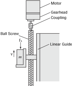
- Total Mass of Table and Load
- m = 45 [kg]
- Travel Speed of Table
- V = 15 ± 2 [mm/s]
- External Force
- FA = 0 [N]
- Ball Screw Inclination Angle
- θ = 90 [˚]
- Overall Length of Ball Screw
- LB = 800 [mm]
- Shaft Diameter of Ball Screw
- DB = 20 [mm]
- Ball Screw Lead
- PB = 5 [mm]
- Travel Distance per Ball Screw Revolution
- A = 5 [mm]
- Ball Screw Efficiency
- η = 0.9
- Ball Screw Material
- Iron (density ρ = 7.9 × 10³ [kg/m3])
- Internal Friction Coefficient of Preload Nut
- μ0 = 0.3
- Friction Coefficient of Sliding Surface
- μ = 0.05
- Motor Power Supply
- Single-Phase 100 VAC 60 Hz
- Operating Time
- Intermittent operation 5 hours per day
Load Holding Required While Stopping for Repeated Start/Stop
(2) Determine the Gear Ratio of Gearhead
Since the rated speed for the electromagnetic brake motor (4-pole) at 60 Hz is 1450-1550 [r/min], select a gearhead gear ratio within this range.
Select a gear ratio of i = 9.
(3) Calculate the Required Torque TM [N·m]
Consider the safety factor Sf = 2.
Select an electromagnetic brake motor and gearhead satisfying the permissible torque of gearhead based on the calculation results (gear ratio i = 9, load torque TL = 0.86 [N·m]) obtained so far.
Here, 4RK25GN-AW2MJ and 4GN9K are tentatively selected as the motor and gearhead respectively, by referring to the specifications.
Convert this load torque to a value on the motor output shaft to obtain the required torque TM.
(Gearhead 4GN9K transmission efficiency ηG = 0.81)
The starting torque of the 4RK25GN-AW2MJ motor selected earlier is 140 [mN·m]. Since this is greater than the required torque of 118 [mN·m], this motor can start the mechanism.
Also confirm whether the electromagnetic brake can hold the gravitational load exerted during stopping.
Here, the load is assumed to be equivalent to the load torque calculated earlier.
Torque T'M
The static friction torque of the electromagnetic brake for the previously selected 4RK25GN-AW2MJ is 100 [mN·m], which meets the required torque of 95.6 [mN·m] for load holding.
(4) Check the Load Inertia J [kg·m2]
Inertia of Ball Screw
Inertia of Table and Load
Calculate the load inertia for the gearhead output shaft J.
Here, permissible load inertia JG for gearhead 4GN9K with a gear ratio 9 is given by the following formula.
Therefore, J < JG, the load inertia is less than the permissible value and there is no problem. There is margin for the torque, so the travel speed is checked with the rotation speed under no load (approximately 1750 r/min).
This confirms that the motor meets the specifications.
Based on the above, 4RK25GN-AW2MJ and 4GN9K are selected as the motor and gearhead, respectively.
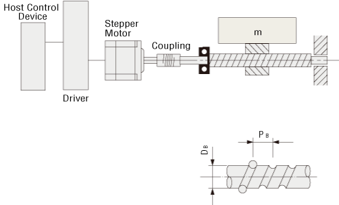
For αSTEP/Stepper motors
(1) Specifications and Operation Conditions of the Drive Mechanism
- Total Mass of Table and Load
- m = 40 [kg]
- Friction Coefficient of Sliding Surface
- μ = 0.05
- Ball Screw Efficiency
- η = 0.9
- Internal Friction Coefficient of Preload Nut
- μ0 = 0.3
- Shaft Diameter of Ball Screw
- DB = 15 [mm]
- Overall Length of Ball Screw
- LB = 600 [mm]
- Ball Screw Material
- Iron (density ρ = 7.9 × 10³ [kg/m3])
- Ball Screw Lead
- PB = 15 [mm]
- Required Resolution
(Feed per pulse) - Δl = 0.03 [mm/step]
- Feed Amount
- l = 180 [mm]
- Positioning Time
- t0 = Within 0.8 seconds
- Inclination Angle
- θ = 0 [˚]
(2) Calculate the Required Resolution θS
αSTEP AZ Series can be used.
Changing or setting the resolution is possible.
The factory setting resolution can be changed from 0.36˚/pulse → 0.72˚/pulse.
(3) Determine an Operating Pattern
① Calculate the number of operating pulses A [Pulse]
② Determine the acceleration (deceleration) time t1 [s]
An acceleration (deceleration) time of 25 % of the positioning time is appropriate.
③ Calculate the operating pulse speed f2 [Hz]
![③ Calculate the operating pulse speed f2 [Hz]](/sites/default/files/image/tech/calculation/sizing-motor06/tech-calculation-sizing-motor06_03_en.gif)
④ Calculate the operating speed NM [r/min]
(4) Calculate the Required Torque TM [N·m]
① Calculate the load torque TL [N·m]
② Calculate the acceleration torque Ta [N·m]
②-1 Calculate the load inertia JL [kg·m2] (Refer to formula)
Inertia of Ball Screw
Inertia of Table and Load
Load inertia
②-2 Calculate the acceleration torque Ta [N·m]
The formula for calculating acceleration torque with pulse speed is shown below. Calculation results are the same.
③ Calculate the required torque TM [N·m]
Safety factor Sf = 2.
(5) Select a Motor
① Tentative Motor Selection
| Product Name | Rotor Inertia [kg·m2] | Required Torque [N·m] |
|---|---|---|
| AZM66AC | 370 x 10-7 | 0.48 |
② Determine the Motor From the Speed - Torque Characteristics
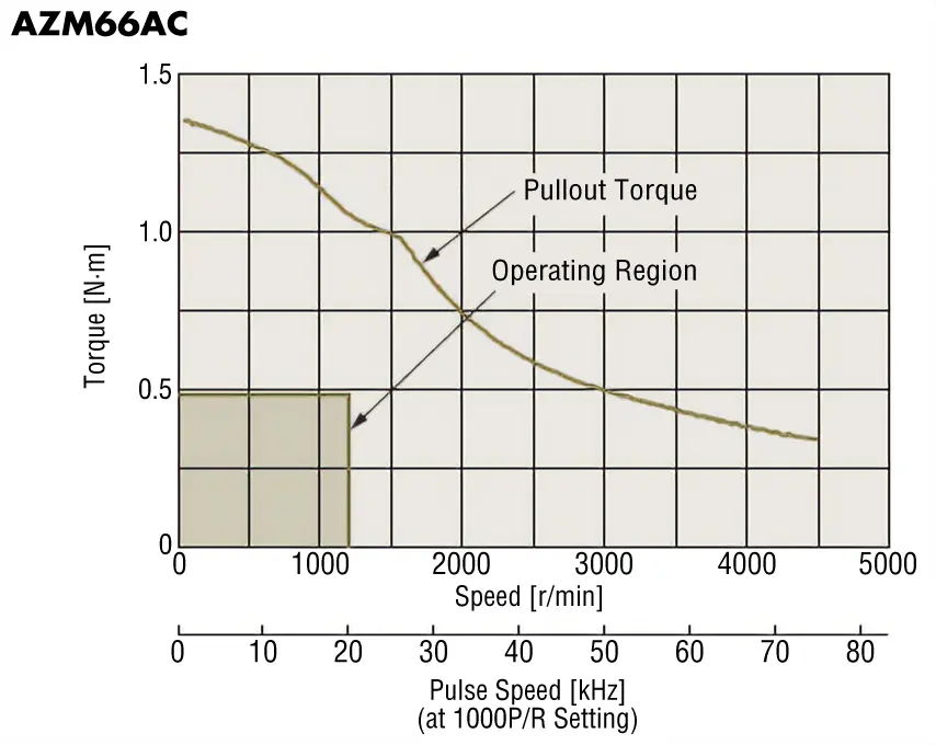
Since the duty region of the motor (operating speed and required torque) falls within the pullout torque of the speed - torque characteristics, the motor can be used.
(6) Check the Inertia Ratio
Refer to formulas and reference values
AZM66AC is 30 or less, if the calculated inertia ratio is 6.8, then operation of that motor is possible.
For Servo Motors
(1) Specifications and Operation Conditions of the Drive Mechanism
The following figure is an example of how to select a servo motor to drive a single axis table:
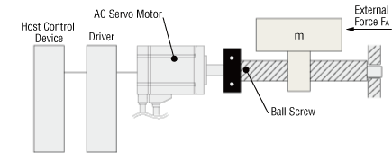
- Maximum Speed of Table
- VL = 0.2 [m/s]
- Resolution
- Δl = 0.02 [mm]
- Motor Power Supply
- Single-Phase 100 VAC
- Total Mass of Table and Load
- m = 100 [kg]
- External Force
- FA = 29.4 [N]
- Friction Coefficient of Sliding Surface
- μ = 0.04
- Ball Screw Efficiency
- η = 0.9
- Internal Friction Coefficient of Preload Nut
- μ0 = 0.3
- Shaft Diameter of Ball Screw
- DB = 25[mm]
- Overall Length of Ball Screw
- LB = 1000 [mm]
- Ball Screw Lead
- PB = 10 [mm]
- Ball Screw Material
- Iron (density ρ = 7.9 × 10³ [kg/m3])
- Operating Cycle
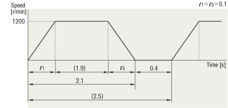
- Operation for 2.1 seconds/stopped for 0.4 seconds (repeated)
- Acceleration/Deceleration Time
- t1 = t3 = 0.1 [s]
(2) Calculate the Required Resolution θ
Calculate the motor resolution from the resolution required for the table drive.
The resolution of the NX Series, θM = 0.36˚/pulse, satisfies this requirement.
(3) Determine an Operating Pattern
Calculate the motor rotation speed (NM) using the formula below.
Determine the speed pattern using NM, the operating cycle and the acceleration/deceleration time.
(4) Calculate the Load Torque TL [N·m]
Operation Direction Load
Load torque of motor shaft conversion
Here, the ball screw preload \(\displaystyle F_0 = \frac{1}{3} \ F \ \).
(5) Calculate the Load Inertia JL [kg·m2]
Inertia of Ball Screw
Inertia of Table and Load
Load inertia
(6) Tentative Servo Motor Selection
Safety factor Sf = 1.5.
Therefore, select the servo motor which has a speed of 1200 [r/min], outputs the rated torque 0.195 [N·m] or more and whose permissible load inertia is 5.56 × 10⁻⁴ [kg·m2] or more.
→ NXM620A+NXD20-A
Rated speed N = 3,000 [r/min]
Rated torque TM = 0.637 [N·m]
Rotor inertia J0 = 0.162 × 10⁻⁴ [kg·m2]
Permissible load inertia J = 8.1 × 10⁻⁴ [kg·m2]
Maximum instantaneous torque TMAX = 1.91 [N·m]
The above values are appropriate.
(7) Calculate the Acceleration Torque Ta [N·m] and Deceleration Torque Td [N·m]
Calculate the acceleration/deceleration torque using the formula below.
(8) Calculate the Required Torque T [N·m]
The required torque is less than the maximum instantaneous torque of NXM620A+NXD20-A of 1.91 [N·m], so the NXM620A+NXD20-A can be used.
(9) Determine a Torque Pattern
Determine a torque pattern using operating cycle, acceleration/deceleration torque, load torque and acceleration time.
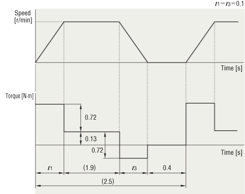
(10) Calculate the Effective Load Torque Trms [N·m]
Calculate the effective load torque Trms using the torque pattern and formula below.
Here, t1 + t2 + t3 = 2.1 [s] from the operating cycle and t1 = t3 = 0.1 for acceleration and deceleration time. Therefore, t2 = 2.1 − 0.1 × 2 = 1.9 [s]
The ratio (effective load safety factor) of Trms and the rated torque of servo motor TM is expressed by the formula below.
Generally, a motor can operate at an effective load safety factor of 1.5∼2 or more.