Selecting a Motor: Selection Example - Index Mechanism
(1) Specifications and Operation Conditions of the Drive Mechanism
Geared stepper motors are ideal for systems with large inertia, such as index tables.
- Table Diameter
- DT = 300 [mm]
- Table Thickness
- LT = 5 [mm]
- Table Materials
- Aluminum (density ρ = 2.8 × 10³ [kg/m3])
- Load Diameter
- DW = 40 [mm]
- Load Thickness
- LW = 30 [mm]
- Load Quantity
- 10 pieces (Every 36˚ arrangement)
- Load Materials
- Aluminum (density ρ = 2.8 × 10³ [kg/m3])
- Distance From Center of Table to Center of Load
- l = 120 [mm]
- Positioning Angle
- θ = 36˚
- Positioning Time
- t0 = 0.25 seconds
The RKII Series PS Geared Type (gear ratio 36, resolution/pulse = 0.02˚) can be used.
For the PS geared type, up to the maximum instantaneous torque can be used for inertia drive start/stop torque.
- Gear Ratio
- i = 36
- Resolution/Pulse
- θS = 0.02˚
(2) Determine an Operating Pattern
① Calculate the Number of Operating Pulses A [pulse]
② Determine the Acceleration (Deceleration) Time t1 [s]
An acceleration (deceleration) time of 25 % of the positioning time is appropriate.
However, here we will use t1 = 0.1 [s].
③ Calculate the Operating Pulse Speed f2 [Hz]
④ Calculate the Operating Speed NM [r/min]
![④ Calculate the Operating Speed NM [r/min]](/sites/default/files/image/tech/calculation/sizing-motor08/tech-calculation-sizing-motor08_02_en.gif)
(3) Calculate the Required Torque TM [N·m]
① Calculate the Load Torque TL [N·m]
Friction load is negligible and therefore omitted. The load torque is assumed as 0.
TL = 0 [N·m]
② Calculate the Acceleration Torque Ta [N·m]
②-1 Calculate the Load Inertia JL [kg·m2]
(Refer to page I-4 for formula)
Inertia of table
Inertia of load
(Around the central axis of the load)
Load Mass
Inertia of load JW [kg·m2] relative to the center of rotation can be calculated from distance l [mm] between the center of load and center of table rotation, mass of load mW [kg], and inertia of load JW1 [kg·m2] around its central axis.
Since the number of loads, n = 10 [pcs],
Inertia of load
(Around the center of table rotation)
Load inertia
②-2 Calculate the Acceleration Torque Ta [N·m]
Calculate the acceleration torque of the gearhead output shaft.
The formula for calculating acceleration torque with pulse speed is shown below.
Calculation results are the same.
③ Calculate the Required Torque TM [N·m]
Calculate using a safety factor of Sf = 2.
(4) Select a Motor
① Tentative Motor Selection
| Product Name | Rotor Inertia [kg·m2] | Required Torque [N·m] |
|---|---|---|
| PKE543AC-PS36+RKSD503-AD | 30 x 10-7 | 2.55 |
② Determine the Motor From the Speed - Torque Characteristics
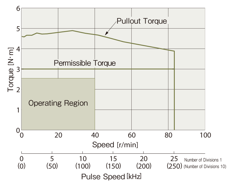
With the PS geared type, acceleration torque up to the maximum instantaneous torque range can be used when starting or stopping load inertia.
Since the duty region of the motor (operating speed and required torque) falls within the pullout torque of the speed - torque characteristics, the motor can be used.
Check the inertia ratio to ensure that the selection is correct.
(5) Check the Inertia Ratio
Refer to formulas and reference values
The PKE543AC-PS36 has a gear ratio of 36, therefore, the inertia ratio is calculated as follows.
PKE543AC-PS36 motor is the equivalent of the PKE543AC motor. Since the inertia ratio is 30 or less, if the inertia ratio is 6.83, motor operation is deemed to be possible.