Selecting a Motor: Selection Example - Winding Mechanism
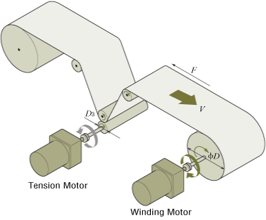
This is a selection example for using winding equipment with a torque motor.

- *Products suitable for use with winding mechanisms are listed here.
(1) Specifications and Operation Conditions of the Drive Mechanism
Winding Roller Diameter ϕD
- Diameter at the Beginning of Winding
- D1 = 15 [mm] = 0.015 [m]
- Diameter at End of Winding
- D2 = 30 [mm] = 0.03 [m]
- Tension Roller Diameter
- D3 = 20 [mm] = 0.02 [m]
- Winding Speed
- V = 47 [m/min] (constant)
- Tension
- F = 4 [N] (constant)
- Power Supply
- Single-Phase 100 VAC, 50 Hz
- Operation Time
- Continuous
(2) Selection of Winding Motors
In general, a winding motor must satisfy the following conditions.
- Winding speed is constant
- Constant tension is applied to prevent sagging of the material.
To meet the above conditions, the following points must be given consideration when selecting a motor.
- Since the winding diameter is different between the start and end of winding, the motor speed must be varied according to the winding diameter to keep the winding speed constant.
- If the tension is constant, the required motor torque is different between the start and end of winding. Accordingly, the torque must be varied according to the winding diameter.
Torque motors have characteristics that are suitable for these conditions.
① Calculate the Rotation Speed
Calculate the rotation speed N1 required at the start of winding.
Calculate the rotation speed N2 required at the end of winding.
② Calculate the Required Torque
Calculate the torque T1 required at the start of winding.
Calculate the torque T2 required at the end of winding.
This winding motor must meet the following conditions.
- Start of Winding
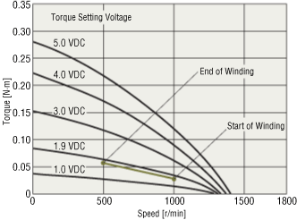
- Rotation Speed N1 = 1000 [r/min], Torque T1 = 0.03 [N·m]
- End of Winding
- Rotation Speed N2 = 500 [r/min], Torque T2 = 0.06 [N·m]
③ Select a Motor
Check the speed - torque characteristics
Select a motor that meets the required conditions specified above from the torque motor TM Series. If the required conditions are plotted on the Speed - Torque Characteristics diagram for 4TK10A-AW2J+TMP-1, it is clear that the conditions roughly correspond to the characteristics at a torque setting voltage 1.9 VDC.
Speed - Torque Characteristics

Check the operation time
4TK10A-AW2J+TMP-1 has a 5 minutes rating when the torque setting voltage is set to 5.0 VDC and a continuous rating when it is set to 1.9 VDC. Under the conditions given here, the torque setting voltage is 1.9 VDC max., indicating that the motor can be operated continuously.
Note
- When using a torque motor in continuous operation for winding, ensure the operating conditions are where the torque motor’s service rating is for continuous operation.
(3) Selection of a Tension Motor
When winding, if tension is not applied, the material sags and cannot be wound neatly. Torque motors can also be used as tension motors because of their reverse-phase brake characteristics.
For the winding equipment above, the tension motor is selected as follows.
① Calculate the Required Rotation Speed N3
② Calculate the Required Torque T3
③ Select a Motor
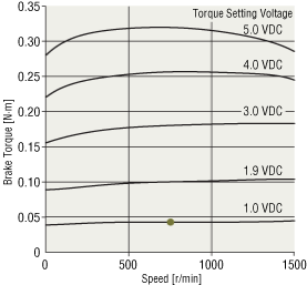
Select a motor that meets the required conditions specified above from the torque motor TM Series . If the required conditions are plotted on the speed - brake torque characteristics diagram* for the 4TK10A-AW2J+TMP-1 reverse-phase brake, it is clear that the conditions roughly correspond to the characteristics at a torque setting voltage of 1.0 VDC.
Speed - Brake Torque Characteristics With Reverse-Phase Brake

Note
- When used in continuous operation as a brake, the temperature rise will vary depending on the rotation speed and torque setting voltage used. Be sure to keep the temperature of the motor case at 90 °C max.
Based on confirmation above, the 4TK10A-AW2J+TMP-1 motor can be used for both winding and tension applications.
- *Please contact the nearest Oriental Motor branch office, sales office or customer support center for information on the speed - brake torque characteristics of each product.