Selection Calculations: For Cooling Fans; Selection Example - Ventilation and Cooling of Control Cabinet -
Control Cabinet Specifications
| Item | Code | Specifications | |
|---|---|---|---|
| Installation environment | General factory | ||
| Control cabinet | Size | W H D |
Width: 700 mm Height: 1000 mm Depth: 400 mm |
| Surface area | S | 2.37 m2 | |
| Material | SPCC | ||
| Overall heat transfer coefficient | U | 5 W/(m2·K) | |
| Permissible temperature rise | ΔT | 20 °C Equipment ambient temperature T1: 25 °C Internal permissible temperature T2: 45 °C |
|
| Total heat generation | Q | 450 W | |
| Power supply | 50 Hz 100 VAC | ||
Calculate the Required Values for Selection
- Calculate the effective surface area of the equipment (heat radiation area) S
The method for calculating the effective surface area of the equipment is as follows:
| Classification of Installation Locations | Formulas |
|---|---|
| When the entire perimeter of the equipment is open | S = 1.4 × W · D + 1.8 × D · H + 1.8 × W · H |
| When the back of the equipment is against a wall | S = 1.4 × W · D + 1.8 × D · H + 1.4 × W · H |
| When heat radiation on one side of the equipment is obstructed (e.g. by connecting equipment) | S = 1.4 × W · D + 1.4 × D · H + 1.8 × W · H |
| When heat radiation is obstructed at the back and one side of the equipment | S = 1.4 × W · D + 1.4 × D · H + 1.4 × W · H |
| When heat radiation on both sides of the equipment is obstructed (e.g. by connecting equipment) | S = 1.4 × W · D + 1.0 × D · H + 1.8 × W · H |
| When heat radiation is obstructed at the back and both sides of the equipment | S = 1.4 × W · D + 1.0 × D · H + 1.4 × W · H |
| When heat radiation is obstructed in all areas except the front of the equipment | S = 0.7 × W · D + 1.0 × D · H + 1.4 × W · H |
Here, we assume that the entire perimeter of the equipment is open.
- Effective surface area S of the equipment
-
1.4 × W · D + 1.8 × D · H + 1.8 × W · H
1.4 × 0.7 × 0.4 + 1.8 × 0.4 × 1.0 + 1.8 × 0.7 × 1.0
2.37 [m2]
(1) Calculating the Required Air Flow
Here, both the method of calculation and a simplified method using graphs are explained.
How to Determine by Calculation
When calculating the required air flow, the internal pressure loss must be taken into account.
Since the pressure loss inside the control cabinet is generally unknown, the air flow at the operating point is assumed to be 50 % of the maximum air flow, and a safety factor Sf = 2 is considered.
How to Determine by Graph
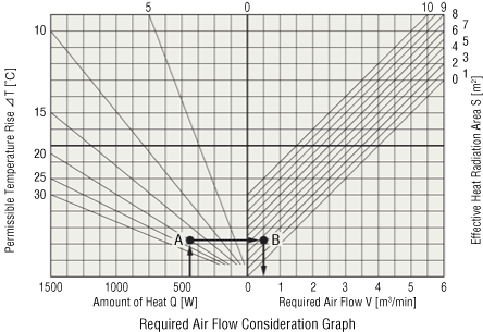
- ①
- Find the intersection point A of heat generation Q 450 W and permissible temperature rise value ΔT 20 °C.
- ②
- Draw a line parallel to the horizontal axis, starting from the intersection point A.
- ③
- Find the intersection point B between the parallel line and the surface area S 2.37 m2.
- ④
- Draw a perpendicular line from point B on the graph to the horizontal axis to determine the required air flow, approximately about 0.5 [m3/min].
- ⑤
- For the reasons discussed above, taking into account a safety factor Sf of 2, the required air flow which can be derived is 1.00 [m3/min].
(2) Selecting a Cooling Fan
Based on the results of these considerations, select the C-MU1238B-11B-PSLG enclosure fan module.
C-MU1238B-11B-PSLG Specifications
| Voltage V |
Frequency Hz |
Input Power W |
Current A |
Rotation speed r/min |
Maximum air flow m3/min |
Maximum static pressure Pa |
Noise level dB (A) |
|---|---|---|---|---|---|---|---|
| 100 | 50 | 15.2 | 0.21 | 2300 | 1.08 | 41 | 40 |
The enclosure fan module is a product that integrates an axial flow fan with accessories (cover, filter media, frame, and finger guard to protect against foreign particles, dust, and water droplets). It is ideal for cooling control cabinets because it not only shuts out the intrusion of foreign particles with a filter, but also allows for easy installation and maintenance.