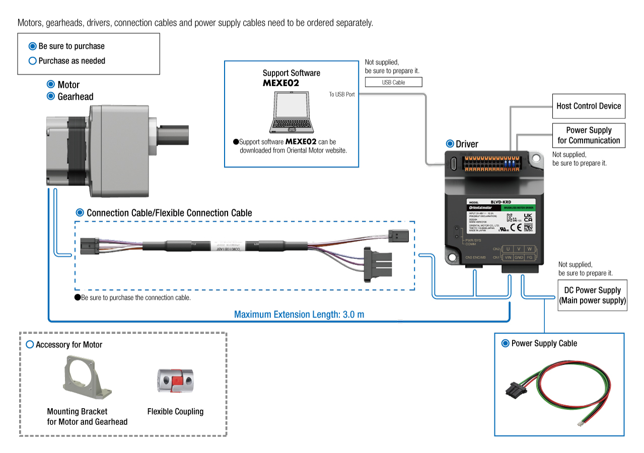
Brushless Motors BLV Series R Type
BLMR260HK-5CS+BLVD-KRD
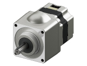
Motor
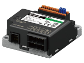
Control Circuit

Connection Cable (Motor~Control Circuit)
Power Supply Cable (Control Circuit~Power Supply)
| Product Classification | Product Name | List Price | Shipping Date |
|---|---|---|---|
| Motor | BLMR260HK-5CS | 362.00 € | Up to 5 pcs Estimated Ship 3weeks |
| Control Circuit | BLVD-KRD | 393.00 € | Up to 5 pcs Estimated Ship 3weeks |
Included
- Motor: Mounting Screws, Parallel Key
Control Circuit: None
Specifications
Characteristics
Speed - Torque Characteristics
Dimensions
Geared Motor
Control Circuit
Connection Cable (When Selected)
Power Supply Cable (When selected)
Data Download
Other Specifications
Common Specifications
| Item | Specifications |
|---|---|
| Input Signals | 4 points, Photocoupler input method |
| Output Signals | 2 points, Photocoupler and open-collector output |
| Main Operation Functions | Continuous operation, positioning operation, JOG operation, return-to-home operation |
| Operation Data Setting Number | 256 Points |
| Setting Tool | Support Software MEXE02 |
| Maximum Extension Distance | Distance between motor and driver: 3.5 m* (when a connection cable (sold separately) is used) |
- * 60 W type is 3.0 m.
Communication Specifications
Power supply for communication*
| Power supply current capacity | Input power supply voltage |
|---|---|
| 0.2 A or more | 24-48 VDC |
- * For the 24 VDC 400 W type, a power supply for communication is not required.
RS-485 Communication Specifications
| Electrical Characteristics | EIA-485 compliant Using twisted-pair wires, the total extension distance of the communication cable should be no more than 10 m. * |
|---|---|
| communication mode | Half duplex Asynchronous mode (Data: 8-bits, Stop bit: 1-bit/2-bits, Parity: none/even/odd) |
| Transmission Rate | Select from 9,600 bps, 19,200 bps, 38,400 bps, 57,600 bps, 115,200 bps, 230,400 bps (initial value) |
| Protocol | Modbus RTU Mode |
| Connection Type | A maximum of 31 units can be connected to a single host controller. |
- * If a specific wiring and layout causes the motor cable or power supply cable to generate a noise problem, shield the cable or use ferrite cores.
CANopen Communication Specifications
| Electrical Characteristics | ISO 11898 compliant Please use a CAN-BUS cable. |
|---|---|
| Communication Protocol | CANopen |
| Communication Profile | Compliant with CiA DS301 Version 4.2.0 |
| Device Profile | CiA DSP402 Version 4.0.0 compliant |
| Node ID | 1~127 |
| Bit Rate | Select from 1 Mbps, 800 kbps, 500 kbps (initial value), 250 kbps, 125 kbps, 50 kbps, 20 kbps, 10 kbps |
| Maximum Bus Length | 25 m (maximum bus length at 1 Mbps) |
| Communication Object | NMT (Network Management) SDO (Service Data Object: 1 SDO server) PDO (Process Data Object: 4 Receive-PDO, 4 Transmit-PDO) EMCY (Emergency Object) SYNC(Synchronization Object) |
| Modes of operation | Profile velocity mode (pv) Profile position mode (pp) Homing mode (hm) |
General Specifications
| Item | Motor | Driver | |
|---|---|---|---|
| Insulation Resistance | 100 MΩ or more when a 500 VDC megger is applied between the windings and the case after continuous operation*1 under normal ambient temperature and humidity. |
After continuous operation under normal ambient temperature and humidity, the measurement value between the power supply input and the heat sink is min. 100 MΩ using a 500 VDC megger. |
|
| Dielectric Strength | After continuous operation*1 at normal ambient temperature and humidity, no abnormality is observed even when 50 Hz, 0.5 kVAC is applied between the windings and the case for 1 minute. |
After continuous operation at normal ambient temperature and humidity, no abnormality is observed even when 50 Hz, 0.5 kVAC is applied between the power supply input and the heat sink for 1 minute. |
|
| Temperature Rise | After rated continuous operation*1 at normal ambient temperature and humidity, the measured value using the thermocouple method is 60 °Cmax. for the temperature rise of the coils and 50 °C max. 50 °C*2. for the temperature rise on the case surface. |
After rated continuous operation at normal ambient temperature and humidity, the measurement value of the temperature rise of the heat sink is 50 °C max. using the thermocouple method. |
|
| Operating Environment | Ambient Temperature | 0~+40 °C (Non-freezing) | 0~+40 °C (Non-freezing)*3 |
| Ambient Humidity | 85 % max. (Non-condensing) | ||
| Altitude | Less than 1000 m above sea level | ||
| Atmosphere | No corrosive gases or dust Should not be exposed to water or oil. Cannot be used in a radioactive area, magnetic field, vacuum, or other special environments. |
||
| Vibration | Not subject to continuous vibration or excessive shock In conformance with JIS C 60068-2-6, "Sine-wave vibration test method" Frequency range: 10~55 Hz, Single amplitude: 0.15 mm Sweep direction: 3 directions (X, Y, Z) Number of sweeps: 20 |
||
| Storage Conditions *4 | Ambient Temperature | -20~+70 °C (non-freezing) | -25~+70 °C (non-freezing) |
| Ambient Humidity | 85 % max. (Non-condensing) | ||
| Altitude | Less than 3000 m above sea level | ||
| Atmosphere | No corrosive gases or dust Should not be exposed to water or oil. Cannot be used in a radioactive area, magnetic field, vacuum, or other special environments. |
||
| Thermal Class | UL/CSA Standards: 105 (A), EN Standards: 120 (E) | − | |
| Degree of Protection | IP40 | IP20 | |
- *1
- The 400 W type has a 30 minutes rating.
- *2
-
For round shaft types, attach to a heat sink (Material: aluminum) of one of the following sizes to maintain a motor case surface temperature of 90 °C max.
60 W type: 135 × 135 mm 5 mm thickness
100 W type: 165 × 165 mm 5 mm thickness
200 W type: 200 × 200 mm 5 mm thickness
400 W type: 250 × 250 mm 6 mm thickness - *3
- Install the driver to a location that has the same heat radiation capability as an aluminum metal plate.
BLVD-KRD: 200 x 200 mm 2 mm thickness,BLVD-KBRD: 350 x 350 mm 2 mm thickness - *4
- The value for storage condition applies to short periods such as the period during transport.
- Do not measure insulation resistance or perform a dielectric strength test the motor and driver are connected.
Permissible Radial Load and Permissible Axial Load
Parallel Shaft Gearhead
| Product Name | Gear Ratio | Permissible Radial Load | Permissible Axial Load Load N |
||
|---|---|---|---|---|---|
| 10 mm From the End of the Output Shaft N |
20 mm From the End of the Output Shaft N |
||||
| BLMR460 | 5 | At 1~3000 r/min | 200 | 250 | 100 |
| At 4000 r/min | 180 | 220 | |||
| 10, 15, 20 | At 1~3000 r/min | 300 | 350 | ||
| At 4000 r/min | 270 | 330 | |||
| 30, 50, 100, 200 | At 1~3000 r/min | 450 | 550 | ||
| At 4000 r/min | 420 | 500 | |||
| BLMR5100 | 5 | At 1~3000 r/min | 300 | 400 | 150 |
| At 4000 r/min | 230 | 300 | |||
| 10, 15, 20 | At 1~3000 r/min | 400 | 500 | ||
| At 4000 r/min | 370 | 430 | |||
| 30, 50, 100, 200 | At 1~3000 r/min | 500 | 650 | ||
| At 4000 r/min | 450 | 550 | |||
| BLMR6200 BLMR6400 |
5, 10, 15, 20 | At 1~3000 r/min | 550 | 800 | 200 |
| At 4000 r/min | 500 | 700 | |||
| 30, 50 | At 1~3000 r/min | 1000 | 1250 | 300 | |
| At 4000 r/min | 900 | 1100 | |||
| 100, 200 | At 1~3000 r/min | 1400 | 1700 | 400 | |
| At 4000 r/min | 1200 | 1400 | |||
CS Geared Motor
| Product Name | Gear Ratio | Permissible Radial Load | Permissible Axial Load N |
||
|---|---|---|---|---|---|
| 10 mm From the End of the Output Shaft N |
20 mm From the End of the Output Shaft N |
||||
| BLMR260 | 5 | At 1~3000 r/min | 150 | 190 | 70 |
| At 4000 r/min | 130 | 170 | |||
| 10, 15, 20 | At 1~3000 r/min | 200 | 260 | ||
| At 4000 r/min | 180 | 230 | |||
Hollow Shaft Flat Gearhead
| Product Name | Gear Ratio | Permissible Radial Load | Permissible Axial Load Load N |
||
|---|---|---|---|---|---|
| 10 mm From Mounting Surface N |
20 mm From Mounting Surface N |
||||
| BLMR460 | 5, 10 | At 1~3000 r/min | 800 | 660 | 400 |
| At 4000 r/min | 730 | 600 | |||
| 15, 20, 30, 50, 100, 200 |
At 1~3000 r/min | 1200 | 1000 | ||
| At 4000 r/min | 1100 | 910 | |||
| BLMR5100 | 5, 10 | At 1~3000 r/min | 900 | 770 | 500 |
| At 4000 r/min | 820 | 700 | |||
| 15, 20 | At 1~3000 r/min | 1300 | 1110 | ||
| At 4000 r/min | 1200 | 1020 | |||
| 30, 50, 100, 200 | At 1~3000 r/min | 1500 | 1280 | ||
| At 4000 r/min | 1400 | 1200 | |||
| BLMR6200 BLMR6400 |
5, 10 | At 1~3000 r/min | 1230 | 1070 | 800 |
| At 4000 r/min | 1130 | 990 | |||
| 15, 20 | At 1~3000 r/min | 1680 | 1470 | ||
| At 4000 r/min | 1550 | 1360 | |||
| 30, 50, 100 | At 1~3000 r/min | 2040 | 1780 | ||
| At 4000 r/min | 1900 | 1660 | |||
Round Shaft Type
| Product Name | Permissible Radial Load | Permissible Axial Load N |
|
|---|---|---|---|
| 10 mm From the End of the Output Shaft N |
20 mm From the End of the Output Shaft N |
||
| BLMR260 | 70 | 100 | 15 |
| BLMR5100 BLMR5200 BLMR5400 |
150 | 170 | 25 |
Standards
Regulations and Standards Materials
Documents about compliance with regulations and standards can be downloaded from the "Data Download" tab on the product details page.
(The types of files available for download vary by product.)
Explanations of the Global Laws, Regulations and Standards can be found here.
Information about our compliance with safety standards for each of our product models can be found here.
Hazardous Substances
The product does not contain any substances (10 substances) exceeding the regulation values of the RoHS Directive (2011/65/EU, 2015/863/EU).
For more information about compliance with regulations on chemical substances in Oriental Motor's Products, click here.
System Configuration