Speed Control Motor/Brushless Motor Speed - Torque Characteristics of AC Speed Control Motors
AC Speed Control Motors
AC Speed Control Motors generally have speed - torque characteristics as shown in the figure below.
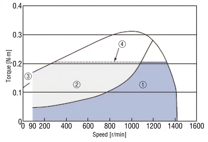
[1] Continuous Duty Region
This is the region where continuous operation is possible within the specification ratings.
[2] Limited Duty Region
[2] Continuous operation within the limited duty region may cause the motor case temperature to exceed 90 °C. When using the product within the limited duty region, make sure that the motor case temperature does not exceed 90 °C.
[3] Starting Torque
This refers to the degree of torque with which the motor can start.
[4] Permissible Torque
[4] This indicates the amount of load torque that can be driven when operating with the gearhead installed. Use is possible within the range shown in the characteristics diagram.
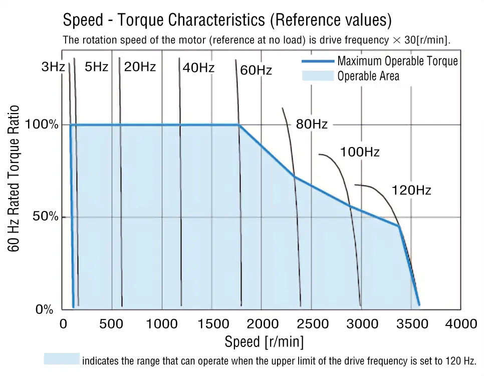
Inverter
In general, inverters have the speed - torque characteristics shown in the figure below.
With inverters, the speed is changed by changing the frequency of the voltage applied to the motor. Consequently, the speed also changes according to the load torque just like the characteristics of induction motors.
Safe-Operation Line and Permissible Torque for Gearhead Connection
With speed control motors, the input changes according to the load and speed.
The higher the load and the lower the rotation speed, the higher the temperature rise.
The graph of the rotation speed-torque characteristics of AC speed control motors and inverters show the "safe-operation line," and the area below this line is called the continuous duty region.
The "safe-operation line" is the limit of continuous operation (30 minutes for reversible motors) that is possible without exceeding the permissible maximum temperature of the motor, and it is determined by the temperature of the motor.
The temperature of the motor case is measured to determine if it can be used under the actual load and rotation speed. In general, if the motor’s case temperature is 90 °C max., continuous operation is possible in according to the insulation class of the winding. However, as the motor’s lifetime will be longer the lower the motor temperature is, it is recommended that it be used under the condition that the motor temperature is kept as low as possible.
When using a gearhead, use a torque less than or equal to the "Permissible Torque When Installing Gearheads." If a gearhead is used and the motor is operated at torques beyond this torque, the life of the motor may be shortened or the motor may be damaged.
Variable Speed Range (Speed Ratio) And Load Factor
When the speed ratio is defined as the ratio of the minimum speed and maximum speed in the variable speed range of an AC speed control motor, the speed ratio becomes as high as 1:15 in a range where the load factor (ratio of the load torque relative to the starting torque) is small (load factor of 40 % in the figure below), thereby expanding the scope of operation.
On the other hand, the speed ratio becomes low when the load factor is large.
Load Factor and Speed Ratio
Now let's look at the relationship between the load factor and the speed ratio. When a motor is actually used, it is often combined with a gearhead. Accordingly, the following explanation also uses an example where a motor is combined with a gearhead.
The table below shows the continuous duty regions and speed ratios of the MSD Series at load factors 40 % and 50 % based on readings from the graph.
While the speed ratio can be large at a load factor of 40 %, the speed ratio grows smaller at 50 %. Thus, in general, AC speed control motors will not allow for a wide range of operation. If you want a wide range of operation, choose a motor with high starting torque (a motor with a larger frame size).
This is not the case with brushless motors, which can be operated over a wider range as shown by the dotted lines.
| Load Factor [%] |
Continuous Duty Region | Speed Ratio | |
|---|---|---|---|
| Min. Speed [r/min] |
Max. Speed [r/min] |
||
| 40 | 18 | 280 | 1:15 |
| 50 | 70 | 275 | Approx. 1:4 |
Speed Ratio When Using a Gearhead with a Large Gear Ratio
Since the starting torque is also limited by the maximum permissible torque of the gearhead, when a gearhead with a high gear ratio is used, the load factor corresponds to the load torque relative to the maximum permissible torque of the gearhead.
In the above example, a gearhead of gear ratio 5 was used. Here we will check the speed ratio when a gearhead of gear ratio 100 is assembled.
The maximum permissible torque of the gearhead 4GN100K of gear ratio 100 is 8 N·m. The table below shows the speed ratios at load factors 30 % and 50 %.
| Load Factor [%] |
Continuous Duty Region | Speed Ratio | |
|---|---|---|---|
| Min. Speed [r/min] |
Max. Speed [r/min] |
||
| 30 | 0.9 | 14.2 | 1:15 |
| 50 | 0.9 | 14.0 | 1:15 |
As shown, if a gearhead of high gear ratio is combined, the speed ratio can be increased without giving too much consideration to the load factor.