AC Motor Structure and Operating Principle of Induction Motors
Structure of Induction Motors
The following figure shows the structure of an induction motor.
- ①
- End Bell
Made by cutting/finishing a die cast aluminum alloy block. It is press-fitted into the motor case.
- ②
- Ball Bearing
- ③
- Rotor
Comprised of laminated magnetic steel sheets and die cast aluminum alloy conductors.
- ④
- Spring
- ⑤
- Stator
Comprised of a stator core made from laminated magnetic steel sheets, windings made of polyester-sheathed copper wire, and insulation film.
- ⑥
- Motor case
Made by cutting/finishing an aluminum alloy die cast block.
Induction Motor Operating Principles
The induction motor (induction machine) is a motor that generates rotational force through the electromagnetic induction effect.
Moreover, among the AC motors we handle, types (classifications) such as reversible motors, torque motors, electromagnetic brake motors, watertight, dust-resistant motors, clutch and brake motors, etc., differ in characteristics and additional functions. However, the operating principle itself is the same as that of an induction motor.
Explanation Using Arago’s Disk
The operating principle of an induction motor is explained using Arago's disk.
-
Arago's Disk
-
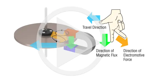
Operating Principles
Replacing Arago’s Disks with Induction Motors
When replacing Arago's disk with actual components of an induction motor, the magnet corresponds to the rotating magnetic field generated by the stator, and the copper plate (conductor) corresponds to the rotor.
The rotor is designed as a cage rotor using aluminum and iron to efficiently extract rotational power.
About Rotating Magnetic Fields
The rotating magnetic field generated in a stator is explained using a stator of a 2-pole motor as an example.
Induction motors have 2 windings, a main winding and an auxiliary winding.
In the induction motors used with actual single-phase power sources, connections are made as follows.
The current from the power supply flows directly to the main winding, and the current flows to the auxiliary winding through the phase advance capacitor.
At that time, the current flowing in the auxiliary winding will become a waveform that is out of phase with the current flowing in the main winding by an electrical angle of 90˚.
At each time from ① to ④, magnetic poles are generated in the stator as shown in the figure above, following the right-handed screw rule. If we look at the time lapse from ① to ② to ③ to ④, the N-pole, which was at a 3 o’clock position in ①, changes as if it is rotating in a clockwise direction, from 3 o’clock to 6 o’clock, 9 o’clock, and 12 o’clock in order.
This is the rotating magnetic field generated in the stator.
Now consider the case where there is no current in the auxiliary winding connected to the phase advancing capacitor. In this case, states ② ④ in the above figure do not occur, and the change is from ① to ③. The position of the N-pole changed 180˚ from 3 o’clock to 9 o’clock, and while it appears like the magnetic pole has rotated, it isn’t clear which direction it rotated in, clockwise or counterclockwise.
When operating with a single-phase power supply in this way, a fixed-directional rotating magnetic field is generated by using a phase advancing capacitor to create a current that is out of phase.
A phase advancing capacitor is not required when operating the motor on a three-phase power supply.
This is because the three-phase power supply has a pre-defined out-of-phase waveform.