Selecting a Hollow Rotary Actuator: Selection of the DGⅡ Series
This section explains the selection calculations for the DGII Series.
1. Calculating the Inertia
Calculate the inertia of the load (load inertia) (Refer to the formulas here).
As a reference, the inertia of the load should be a maximum of 30 times the actuator's inertia (maximum of 10 times for deep-groove ball bearing type).
2. Selecting a Model
- ①
- When there is no friction torque, confirm the positioning time from the load inertia - positioning time graph for the DGⅡ Series.
Refer to here for the load inertia - positioning time graph.
- ②
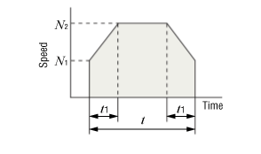
- Determine the positioning time and acceleration/deceleration time.
However, the positioning time should be equal to or greater than the shortest positioning time obtained from the load inertia - positioning time graph, and the acceleration/deceleration time should be t1 × 2 ≦ positioning time.
- ③
-
Determine the starting rotation speed N1, and calculate the operation rotation speed N2 using the following formula.
Set N1 as the low speed [0-n r/min] and do not set it any higher than required.\(\begin{align} N_2 = \frac{\theta - 6 N_1 t_1}{6 ( t - t_1)} \end{align}\)- N 2
- Operation Rotation Speed [r/min]
- θ
-
Positioning Angle[°]
- N 1
- Starting Rotation Speed [r/min]
- t
- Positioning Time [s]
- t 1
- Acceleration (Deceleration) Time [s]
If N1 ≦ N2 ≦ 200 [r/min] is not achieved with the above formula, return to step ① and review the conditions.
3. Calculating the Required Torque
- ①
-
Calculate the acceleration torque using the following formula.
-
- T a
- Acceleration Torque [N·m]
- J 1
- Actuator Inertia [kg·m²]
- J L
- Total Inertia [kg·m²]
- N 2
- Operation Rotation Speed [r/min]
- N 1
- Starting Rotation Speed [r/min]
- t 1
- Acceleration (Deceleration) Time [s]
- ②
-
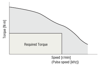
Calculate the required torque. The required torque is the sum of the load torque of the frictional resistance and the acceleration torque of the inertia multiplied by the safety factor.
-
- T
- Required Torque [N·m]
- T L
- Load Torque [N·m]
- T a
- Acceleration Torque [N·m]
- S f
- Safety Factor
Ensure that the safety factor Sf is 1.5 times or more (for the products equipped with AZ Series with a frame size of 130 mm and 48 VDC input, it should be 2 times or more).
- ③
-
Check whether the required torque T is within the rotation speed - torque characteristics. If it does not meet the requirements, return to step ② of "2. Selecting a Model," change the conditions, and recalculate the values.
When switching from speed to pulse speed, use the formula below.
-
- f
- Pulse Speed [Hz]
- N
- Rotation Speed [r/min]
- θ S
- Minimum Step Angle of Output Table [deg/STEP]
4. Calculating the Load Moment and Axial Load
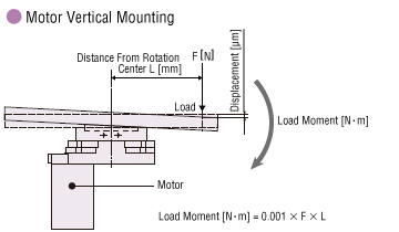
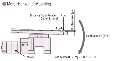
When there is a load on the output table as shown in the diagram below, calculate the load moment and axial load using the formula below, and confirm they are within the specification values.
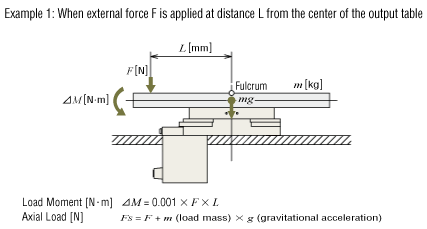
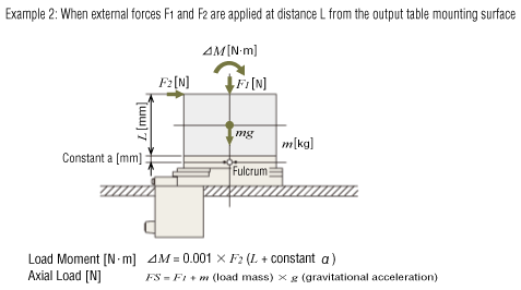
| Product Name | DGM60 |
DGM85R, DGB85R |
DGM130R, DGB130R |
DGM200R |
|---|---|---|---|---|
| Output Table Supporting Bearing |
Deep-groove ball bearing | Cross-roller bearing | ||
| Constant a [mm] | 10 | 20 | 30 | 40 |
| Product Name | Output Table Supporting Bearing |
Permissible Moment [N·m] |
Permissible Axial Load [N] |
|---|---|---|---|
| DGM60 | Deep-groove ball bearing | 2 | 100 |
| DGM85R, DGB85R | Cross-roller bearing |
10 | 500 |
| DGM130R, DGB130R | 50 | 2000 | |
| DGM200R | 100 | 4000 |
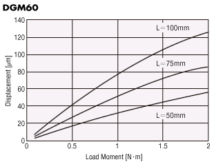
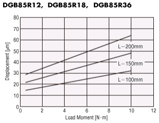
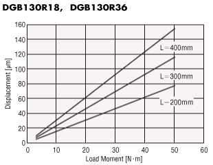
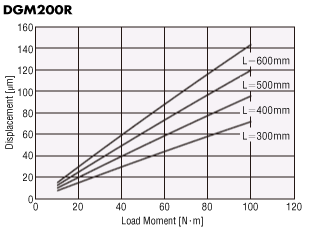
Displacement by Load Moment (Reference value)
The output table will be displaced when it receives a load moment.
The graph plots the displacement which occurs at distance L from the rotation center of the output table when a given load moment is applied in one direction.
The displacement becomes approximately twice the size when the load moment is applied in both the positive and negative directions.
