Selecting a Rack-and-Pinion System: Selecting an L Series Product Equipped With αSTEP AZ Series
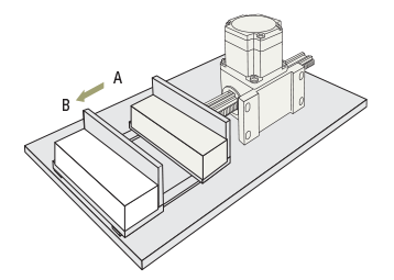
The following parameters are required when selecting rack-and-pinion systems for transporting load from A to B as shown in the figure below.

The required parameters are as follows:
- Load mass (m) or thrust (F)
- Positioning distance (L)
- Positioning time (T)
- Repetitive positioning accuracy
- Maximum stroke
Among the parameters above, the thrust and positioning time can be calculated using the formulas below.
Thrust Formula
① Calculation of the Required Thrust When Accelerating a Load Attached to a Rack
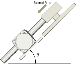
② Calculation of Possible Thrust for Pushing and Pulling
If the external force applied to the load is smaller than F, then push-pull motion is possible.
- Fmax
- Rack-and-pinion system maximum thrust [N]
- Fa
- Required thrust during acceleration/deceleration operation [N]
- F
- Thrust possible for pushing or pulling of external force [N]
- m
- Load mass to be transported on the rack [kg] + rack mass [kg]
- a
- Acceleration [m/s²]
- g
- Gravitational acceleration 9.807 [m/s²]
- μ
- Friction coefficient of the guide supporting the load 0.01
- θ
- Angle formed by the moving direction and the horizontal plane [˚]

Positioning Time Formula
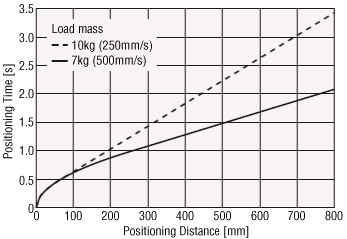
Confirm that the rack-and-pinion system can be positioned in time without problems. This can be done by obtaining a rough positioning time from the graph or by obtaining a fairly accurate positioning time by calculation. Each of the confirmation procedures is explained below.
The actual operating time is subject to a small margin of error, so use the calculation only as a reference.
Example) For LM2

Using Formula Calculations
① Confirm the Operation Conditions
Check the following conditions:
Installation direction, load mass, positioning distance, starting speed, acceleration, operating speed
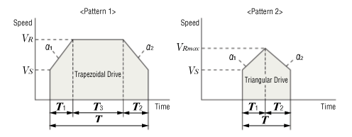
② From the Operation Conditions above, Confirm Whether the Drive Pattern is a Triangular Drive or a Trapezoidal Drive
Calculate the maximum speed of triangular drive from the positioning distance, starting speed, acceleration and operating speed. If the calculated maximum speed is equal to or below the operating speed, the operation is considered a triangular drive. If the maximum speed exceeds the operating speed, the operation is considered a trapezoidal drive.
③ Calculate the Positioning Time
[In case of trapezoidal drive]
[In case of triangular drive]

- VRmax
- Maximum speed calculated for triangular drive [mm/s]
- VR
- Operating speed [mm/s]
- Vs
- Starting speed [mm/s]
- L
- Positioning distance [mm]
- a1
- Acceleration [m/s²]
- a2
- Deceleration [m/s²]
- T
- Positioning time [s]
- T1
- Acceleration time [s]
- T2
- Deceleration time [s]
- T3
- Constant speed time [s]
Other conversion formulas are explained below.
The pulse speed and operating speed can be converted using the formula below. Keep the operating speed below the specified maximum speed.
The number of operating pulses and travel amount can be converted using the formula below.
The acceleration/deceleration rates and acceleration can be converted using the formula below.
The input methods for speed, travel amount, and acceleration vary depending on the host control device. Please calculate according to your usage.