Gearhead/Linear Head: Characteristics of Linear Heads
There are 3 important characteristics of a linear head.
- Rack Speed
- Maximum Transportable Mass
- Holding Force
Rack Speed
The rack speed of the LS linear head and LH linear head is listed as the basic speed in the characteristics table of each product.
The basic speed is calculated based on the synchronous speed of the motor (50 Hz: 1500 r/min). In reality, the rotation speed of the motor varies depending on the size of the load.
When the LS linear head or LH linear head is combined with a speed control motor, the calculation can be performed using the following formula based on the rotation speed of the motor.
- V
- Rack travel speed [mm/s]
- NS
- Rotation speed of motor combined [r/min]
- i
- Gear ratio of the linear head deceleration unit → Table below
- DP
- Pitch circle diameter of pinion [mm] → Table below
Maximum Transportable Mass
If combining with a motor not listed in the characteristic table, you can calculate the thrust from the torque generated by the motor using the following formula.
However, if the gear ratio is large or if the gear is used in the horizontal direction, the calculation shows that the load mass that exceeds the mechanical strength of the gearhead can be driven. Regardless of the travel direction of the rack, the load mass of the linear head should be less than the maximum transportable mass of each type.
- Tm
- Torque of motor [mN·m]*
- F
- Thrust [N]
- W
- Transportable Mass [kg]
- i
- Gear ratio of the linear head deceleration unit → Table below
- η1
- Transmission efficiency by gear ratio → Table below
- DP
- Pitch circle diameter of pinion [mm] → Table below
- η2
- Transmission efficiency of rack and pinion [=0.9]
- *Use the smaller value of the starting torque and the rated torque for the calculation.
The values for maximum transportable mass and calculated thrust in the characteristics table are for horizontal movement of the rack. If the rack is moved vertically, subtract the rack mass (refer to the dimensions) or the force equivalent to the rack mass (rack mass × 9.807) from the value in the characteristics table.
LS Linear Heads
| Product Name | Gear Ratio i |
Transmission Efficiency η1 |
Pitch Circle Diameter of Pinion DP [mm] |
|---|---|---|---|
| 2LSF(B)45-□ | 17.68 | 0.73 | 10.7 |
| 2LSF(B)20-□ | 35.36 | 0.66 | |
| 2LSF(B)10-□ | 86.91 | 0.59 | |
| 4LSF(B)45-□ | 36 | 0.73 | 21.25 |
| 4LSF(B)20-□ | 75 | 0.66 | |
| 4LSF(B)10-□ | 150 | 0.66 |
- A number indicating the stroke is specified where the box □ is located in the product name.
LH Linear Heads
| Product Name | Gear Ratio i |
Transmission Efficiency η 1 |
Pitch Circle Diameter of Pinion D P [mm] |
|---|---|---|---|
| 2LF(B)50N-□ | 17.68 | 0.73 | 12 |
| 2LF(B)25N-□ | 35.36 | 0.66 | |
| 2LF(B)10N-□ | 86.91 | 0.59 | |
| 4LF(B)45N-□ | 36 | 0.73 | 21.25 |
| 4LF(B)20N-□ | 75 | 0.66 | |
| 4LF(B)10N-□ | 150 | 0.66 | |
| 5LF(B)45U-□ | 36 | 0.66 | 24 |
| 5LF(B)20U-□ | 90 | 0.59 | |
| 5LF(B)10U-□ | 180 | 0.59 |
- A number indicating the stroke is specified where the box □ is located in the product name.
Holding Force
For LH linear head 0L type, refer to the product characteristics table. For LS linear heads and LH linear heads, you can calculate them using the following formula based on the holding force of the combined motor.
- FB
- Holding force [N]
- TB
- Holding torque of motor [mN·m]
- i
- Gear ratio of the linear head deceleration unit → Table above
- DP
- Pitch circle diameter of pinion [mm] → Table above
The holding forces in the characteristics table and the calculated holding force values are for the case where the rack is installed horizontally. For vertical installation, subtract the force (rack mass × 9.807) for the rack mass (refer to the dimensions) from the value in the characteristics table.
Play in the LS Linear Head and LH Linear Head Racks (Initial value)
LS Linear Heads
The LS linear head rack is supported by rack bushings in 2 locations on the rack case. Since there is a slight gap between the rack bushing and the rack to allow sliding inside the rack bushing, the rack moves in the direction shown in the figure.
| A, B Direction | 2 mm max. |
| C Direction (Backlash) | 0.5 mm max. |
| D Direction | 0.5˚ max. |
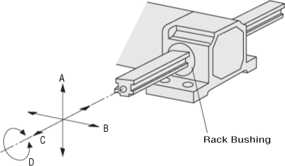
- Play in the A and B directions is measured at 500 mm from the end face of the case.
- Play in the rack will increase with continued use over time. For applications where play may be a problem, please provide an external guide.
LH Linear Heads
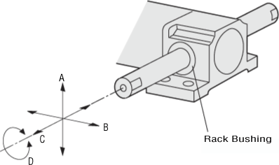
The LH linear head rack is supported by rack bushings in 2 locations on the rack case. Since there is a slight gap between the rack bushing and the rack to allow sliding inside the rack bushing, the rack moves in the direction shown in the figure.
- Play in the A and B directions is measured at 500 mm from the end face of the case. The play in the D direction is greater due to the round shape of the rack.
- Play in the rack will increase with continued use over time. For applications where play may be a problem, please provide an external guide.
| A, B Direction | 2 mm max. |
| C Direction (Backlash) | 0.5 mm max. |
| D Direction | 5˚ max. |
Overrun (Reference value)
LS Linear Heads
| 2LSF(B)10-□ | 2LSF(B)20-□ | 2LSF(B)45-□ | |
|---|---|---|---|
| 2RK6GN-A(C)W2J | 2.3 | 5.7 | 11 |
|
2RK6GN-A(C)W2J
+ Brake Pack SB50W |
0.6 | 1.4 | 2.9 |
| 2RK6GN-A(C)W2MJ | 1.2 | 2.9 | 5.7 |
|
2RK6GN-A(C)W2MJ
+ Brake Pack SB50W |
0.6 | 1.4 | 2.9 |
- The above overrun values are for reference value under no load.
| 4LSF(B)10-□ | 4LSF(B)20-□ | 4LSF(B)45-□ | |
|---|---|---|---|
| 4RK25GN-A(C)W2J | 2.7 | 5.3 | 11 |
|
4RK25GN-A(C)W2J
+ Brake Pack SB50W |
0.7 | 1.3 | 2.8 |
| 4RK25GN-A(C)W2MJ | 1.3 | 2.7 | 5.6 |
|
4RK25GN-A(C)W2MJ
+ Brake Pack SB50W |
0.7 | 1.3 | 2.8 |
- The above overrun values are for reference value under no load.
LH Linear Heads
| Product Name | Overrun |
|---|---|
| 0LF(B)5N-□RA, 0LF(B)5N-□RC | 1.4 (0.3) |
| 0LF(B)10N-□RA, 0LF(B)10N-□RC | 2.8 (0.5) |
| 0LF(B)20N-□RA, 0LF(B)20N-□RC | 4.7 (0.8) |
- The above overrun values are for reference value under no load. The values in parentheses ( ) in the above overruns are for instantaneous stops using the brake pack.
| 2LF(B)10N-□ | 2LF(B)25N-□ | 2LF(B)50N-□ | |
|---|---|---|---|
| 2RK6GN-A(C)W2J | 2.6 | 6.4 | 13 |
|
2RK6GN-A(C)W2J + Brake Pack SB50W |
0.7 | 1.6 | 3.2 |
| 2RK6GN-A(C)W2MJ | 1.3 | 3.2 | 6.4 |
|
2RK6GN-A(C)W2MJ + Brake Pack SB50W |
0.7 | 1.6 | 3.2 |
- The above overrun values are for reference value under no load.
| 4LF(B)10N-□ | 4LF(B)20N-□ | 4LF(B)45N-□ | |
|---|---|---|---|
| 4RK25GN-A(C)W2J | 2.7 | 5.3 | 11 |
|
4RK25GN-A(C)W2J
+ Brake Pack SB50W |
0.7 | 1.3 | 2.8 |
| 4RK25GN-A(C)W2MJ | 1.3 | 2.7 | 5.6 |
|
4RK25GN-A(C)W2MJ
+ Brake Pack SB50W |
0.7 | 1.3 | 2.8 |
- The above overrun values are for reference value under no load.
| 5LF(B)10U-□ | 5LF(B)20U-□ | 5LF(B)45U-□ | |
|---|---|---|---|
|
5RK60GU-A(C)F
5RK90GU-A(C)F |
2.5 | 5.0 | 13 |
|
5RK60GU-A(C)F
+ Brake Pack SB50W 5RK90GU-A(C)F + Brake Pack SB50W |
0.6 | 1.3 | 3.1 |
|
5RK60GU-A(C)MF2
5RK90GU-A(C)MF2 |
1.3 | 2.5 | 6.3 |
|
5RK60GU-A(C)MF2
+ Brake Pack SB50W 5RK90GU-A(C)MF2 + Brake Pack SB50W |
0.6 | 1.3 | 3.1 |
- The above overrun values are for reference value under no load.
- A number indicating the stroke is specified where the box □ is located in the product name.