AC Motors Reversible Motor Operating Time and Temperature Rise
While reversible motors have a '30 minutes rating,' the operating time may vary depending on the operating conditions, even when performing short-term intermittent operations. When using a reversible motor for short-term intermittent operation, there is a large current flow and significant heating during motor start-up and reversal. However, by allowing sufficient time for the motor to be at rest, the natural cooling effect during stops can be substantial, helping to keep the temperature rise of the motor low.
In Case of Intermittent Operation
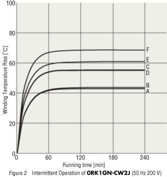
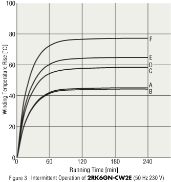
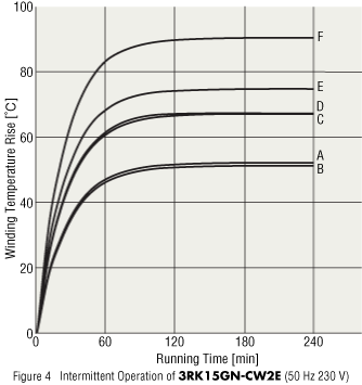
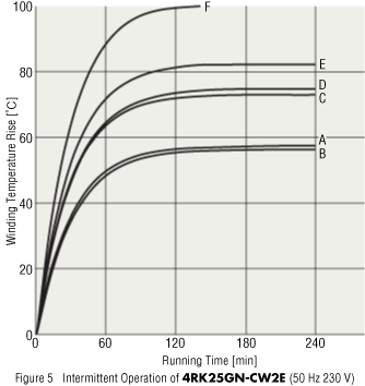
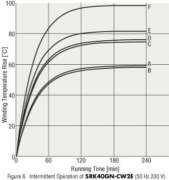
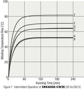
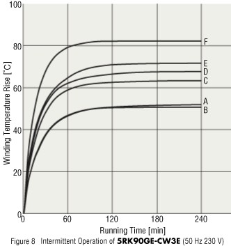
Determine the conditions for intermittent operation as shown in Figure 1, A through E. F indicates the condition of continuous operation. Oriental Motor gathered actual measurements of the temperature rise of our typical reversible motor under these conditions.
Figures 2 through 8 show the results.
When measuring the temperature rise, the motor unit was suspended in midair, with almost no heat conduction, and under no load, which is the most severe condition possible from the perspective of temperature rise in capacitor start and run motors.
However, please note that the time required for starting and reversing may be longer and the temperature rise may be higher, especially if the load is greater than the rated torque of the motor or the load inertia is large.
For example, the temperature rise of 4RK25GN-CW2E should be carefully controlled so that the winding temperature rise is 80 °C max. and the motor case temperature is 90 °C max. for operation.
In Figure 5, for 4RK25GN-CW2E, it is observed that intermittent operation can be continuous (conditions A and B) if the operating time and stopping time are the same. (Conditions C and D are the limits.) Also, the larger the motor's output, the shorter the time becomes.
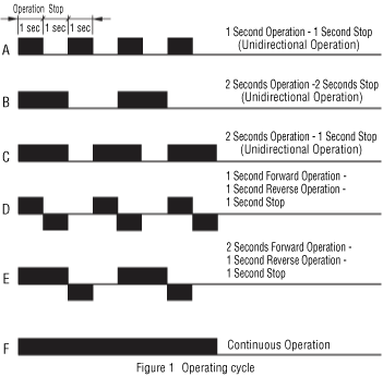
Table 1 shows the size of the heat sink used for temperature rise measurements in Figures 2 through 8.
Table 1: Heat Sink Size
| Product Name | Size (mm) | Thickness (mm) | Materials |
|---|---|---|---|
| 0RK1GN-CW2J | 80 × 80 | 5 | Aluminum |
| 2RK6GN-CW2E | 115 × 115 | ||
| 3RK15GN-CW2E | 125 × 125 | ||
| 4RK25GN-CW2E | 135 × 135 | ||
| 5RK40GN-CW2E | 165 × 165 | ||
| 5RK60GE-CW2E | 200 × 200 | ||
| 5RK90GE-CW3E | 200 × 200 |
When a Heat Sink is Attached.
Table 2 shows the type of heat sinks used for temperature rise measurements in Figure 9.
Based on these measurements, doubling the size of the heat sink will reduce the temperature rise by about 10 °C. Additionally, aluminum has higher thermal conductivity than iron, so the temperature rise is lower. Furthermore, by painting aluminum black, it can be reduced by an additional approximately 5 °C.
The temperature of the motor varies depending on conditions such as load, operating cycle, motor mounting method, and ambient temperature. Making a comprehensive judgment based on all this data can be challenging, so please use it as one of the criteria for evaluation.
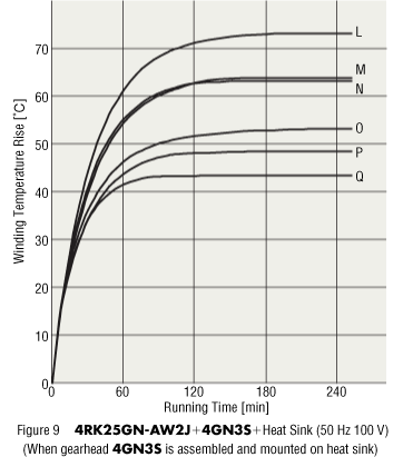
Table 2: Types of Heat Sinks
| Temperature Rise Curve | Types of Heat Sinks | |||
|---|---|---|---|---|
| Size (mm) | Thickness (mm) | Materials | Painting | |
| L | − | − | − | − |
| M | 150 × 150 | 5 | Steel | None |
| N | 150 × 150 | 5 | Aluminum | None |
| O | 300 × 300 | 5 | Steel | None |
| P | 300 × 300 | 5 | Aluminum | None |
| Q | 300 × 300 | 5 | Aluminum | Black |
