Selecting a Compact Electric Cylinder: Calculating the Load Moment
Selection Method
The Load Moment
When loads are transported by the following products, if the position of the center of gravity of the load is offset from the table center, a load moment will act on the linear guide.
- DR Series Table Type, Wide Table Type/DRS2 Series Guide Type
- DR Series Rod Type With Guide
- DRLII Series Guide Type, Table Type
The direction of action applies to 3 directions: pitching (MP), yawing (MY), and rolling (MR), depending on the position of the offset.
Load Moments of DR Series Table Type, Wide Table Type/DRS2 Series Guide Type.
The figure shows the DRS2 Series Guide Type.
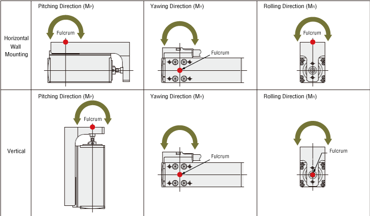
Load Moments of DR Series Rod Type With Guide
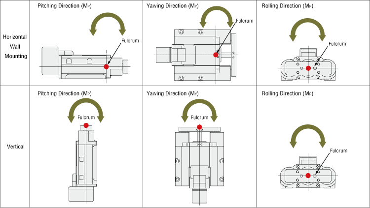
Load Moments of DRLII Series Guide Type

Load Moments of DRLII Series Table Type

Even though the selected electric actuators satisfy the load mass and positioning time requirements, when the center of gravity of the load is overhung from the table's center, the run life may decrease as a result of the load moment. Load moment calculations must be completed and whether the conditions are within specifications values must be checked.
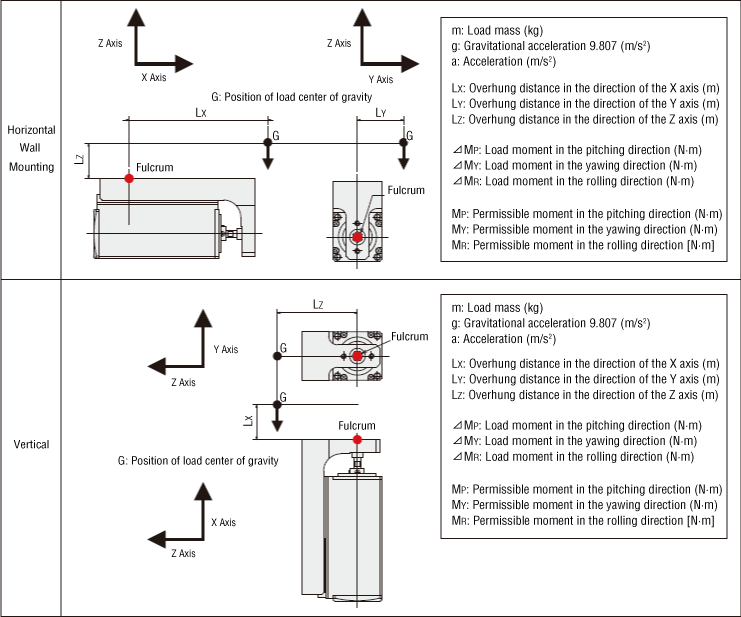
- *In the vertical direction, the center position of the table for calculating the moment will change.
Based on how the workpiece or load is applied, calculate the load moment on the compact electric cylinder to ensure that it does not exceed the permissible moment (maximum load moment), and check that the strength is sufficient.
DR Series Table Type, Wide Table Type/DRS2 Series Guide Type
- *Refer to this page for the DR Series Rod Type With Guide.
The figure shows the DRS2 Series Guide Type.
DRLII Series Guide Type
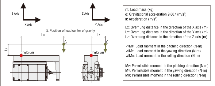
DRLII Series Table Type
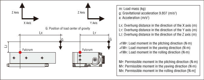
- Load Moment Formula:
When there are several overhung loads, etc., it is determined by the sum of moments from all loads.
- For Multiple Loads (n pieces)
Concept of Load Moment Application
When the load moment is applied during a stop or an operation state, check the dynamic and static moments taking acceleration into account, and compare with the permissible moment (maximum load moment).
DR Series Table Type, Wide Table Type/DRS2 Series Guide Type
- *Refer to this page for the DR Series Rod Type With Guide.
The figure shows the DRS2 Series Guide Type.
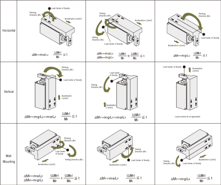
When the load factor of the permissible moment (maximum load moment) for the calculated load moment exceeds 1, it may cause a malfunction or reduce of the expected life.
DRLII Series Guide Type
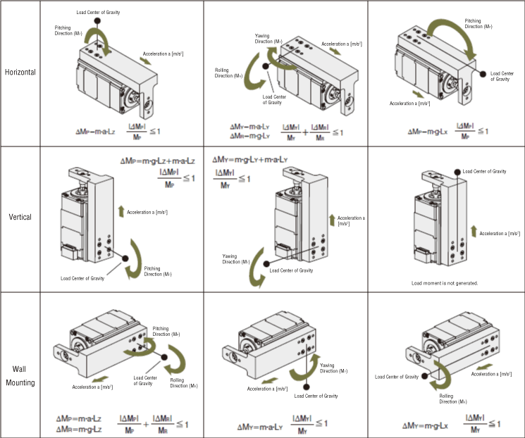
When the load factor of the permissible moment (maximum load moment) for the calculated load moment exceeds 1, it may cause a malfunction or reduce of the expected life.
DRLII Series Table Type
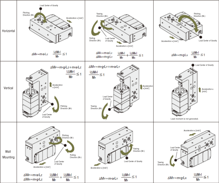
When the load factor of the permissible moment (maximum load moment) for the calculated load moment exceeds 1, it may cause a malfunction or reduce of the expected life.