Selecting an Electric Linear Slide/Electric Cylinder: Tentative Selection of Electric Actuators
Selection Method
(1) Confirming the Required Specifications
Confirm the required specifications for the equipment.

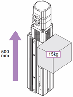
- Load Mass
- m = 15 [kg]
- Positioning Distance
- L = 500 [mm]
- Positioning Time
- T = Within 2 seconds
- Drive Direction
- Vertical
(2) Tentative Selection of Electric Actuators
The following electric actuator is tentatively selected based on the required specifications.
- Product name
- EASM6
- Lead
- 6 mm
- Power Supply Input
- Single-Phase 200 VAC
(3) Confirming the Positioning Time
Check whether the actuator can perform the necessary positioning within the specified time. This can be done by obtaining a rough positioning time from the graph or by obtaining a fairly accurate positioning time by calculation. Each of the confirmation procedures is explained below.
The actual operating time is subject to a small margin of error, so use the calculation only as a reference.
Using the Tool for Calculating the Shortest Positioning Time
For applicable products of Oriental Motor’s electric linear slides and electric cylinders, the approximate positioning time can be calculated by "model" and "operation conditions."
Click here for a tool to calculate the shortest positioning time

Obtaining From a Graph
- ①
-
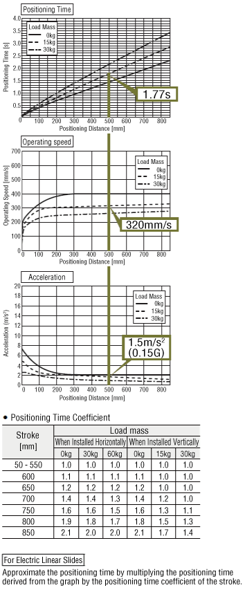
Use the graph to confirm the positioning time necessary for a positioning distance of 500 mm.
Positioning Time: 1.77 s
The requested positioning time of 2 seconds or less is satisfied, so it can be used.
- ②
-
If the positioning time requirement is satisfied, check the operating speed and acceleration.
Operating Speed: 320 mm/s
Acceleration : 1.5 m/s2(0.15 G)
- ③
- If the positioning time requirement is not satisfied, select a different model.

Using Formula Calculations
- ①
-
Confirm operation conditions
Check the following conditions:
Positioning distance, starting speed, acceleration, and operating speed
- ②
-
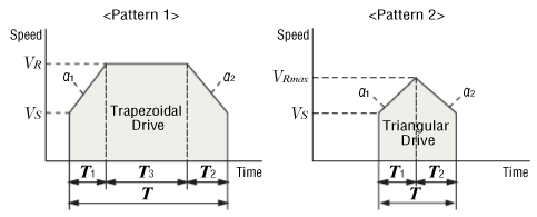
From the operation conditions above, confirm whether the drive pattern is a triangular drive or trapezoidal drive
Calculate the maximum speed of triangular drive from the positioning distance, starting speed, acceleration and operating speed. If the calculated maximum speed is equal to or below the operating speed, the operation is considered a triangular drive. If the calculated maximum speed exceeds the operating speed, the operation is considered a trapezoidal drive.
- ③
-
Calculate the positioning time
[In the case of trapezoidal drive]
[In the case of triangular drive]
-

- VRmax
- Maximum Speed Calculated for Triangular Drive [mm/s]
- VR
- Operating Speed [mm/s]
- Vs
- Starting Speed [mm/s]
- L
- Positioning Distance [mm]
- a1
- Acceleration [m/s²]
- a2
- Deceleration [m/s²]
- T
- Positioning Time [s]
- T1
- Acceleration Time [s]
- T2
- Deceleration Time [s]
- T3
- Constant Speed Time [s]
The actual operating time is subject to a small margin of error, so use the calculation only as a reference.
Other conversion formulas are explained below.
The pulse speed and operating speed can be converted using the formula below. Keep the operating speed below the specified maximum speed.
The number of operating pulses and travel amount can be converted using the formula below.
The acceleration/deceleration rates and acceleration can be converted using the formula below.
The input methods for speed, travel amount, and acceleration vary depending on the host control device. Please calculate according to your usage.
