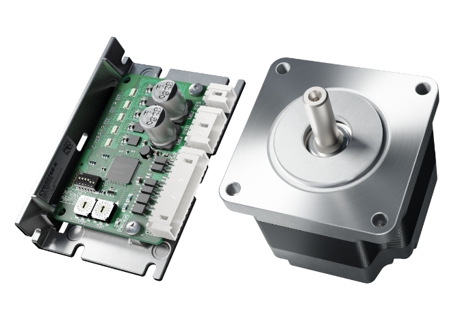
Stepper Motors
Sincronización perfecta con la señal de pulsos para un control de posición de alta precisión. Alto par y bajas vibraciones, adecuados para posicionamientos de corta duración en distancias pequeñas.
Stepper Motors
Overview and Related Information
Overview
Stepper motors enable accurate positioning operation with ease.
These motors are used in various types of equipment for accurate rotation angle and rotation speed control using pulse signals.
Fine and Accurate Positioning
A stepper motor is a motor that rotates with a fixed angle, just like the second hand of a clock. This angle is called a "basic step angle." Oriental Motor offers 5-phase stepper motors with a basic step angle of 0.72˚ and 2-phase stepper motors with a basic step angle of 1.8˚.

Easy Control With Pulse Signals
A system configuration for high precision positioning is shown in the figure below. The rotation angle and rotation speed of the stepper motor can be controlled accurately using pulse signals from the controller.
System Configuration

What is a Pulse Signal?
A pulse signal is an electric signal for which the power supply is repeatedly turned ON and OFF.
1 cycle of ON/OFF is counted as 1 pulse, and when 1 pulse is input, the motor output shaft rotates by 1 step angle.

The Rotation Angle is Proportional to the Number of Pulses
The rotation angle of the stepper motor is proportional to the number of pulse signals (number of pulses) input to the driver.
The relationship of the stepper motor's rotation angle and number of pulses is expressed as follows:
θ = θS × A
- θ
- Rotation angle of motor output shaft [˚]
- θS
- Step angle (resolution) [°/step]*
- A
- number of pulses

The Rotation Speed is Proportional to the Pulse Speed
The rotation speed of the stepper motor is proportional to the speed of pulse signals (pulse frequency) input to the driver.
The relationship of the pulse speed [Hz] and rotation speed [r/min] is expressed as follows:
N = θS / 360 × f × 60
- N
- Rotation speed of motor output shaft [r/min]
- θS
- Step angle (resolution) [°/step]*
- f
- Pulse speed [Hz]
(Number of pulses input per second)
- *For geared motors, this is the step angle (resolution) of the gearhead output shaft.

Compact and High Torque
Stepper motors generate high torque with a compact body.
These features provide excellent acceleration characteristics and responsiveness, which makes these motors quite useful for applications where the motor must be started and stopped frequently.
Also, by using a geared motor, even greater torque can be obtained.
Frequent Starting and Stopping is Possible

Speed - Torque Characteristics (When motor frame size is 60 mm)

The Motor Holds Itself at a Stop Position
Stepper motors have a holding force even when they are stopped, so they do not need to rely on mechanical brakes to maintain the stop position.

Capable of Driving Large Load Inertia
Stepper motors can drive larger load inertia than servo motors of equivalent frame sizes.
Comparison at 30 Times the Rotor Inertia
-

Stepper Motors
Inertia 22.4 x 10⁻⁴ kg·m2
(30 times the rotor inertia)- Load Inertia
- Diameter 169 mm, thickness 10 mm, material aluminum
- Motor
- Frame size 60 mm
Length 90 mm
-

Conventional servo motor
Inertia 4.0 x 10⁻⁴ kg·m2
(30 times the rotor inertia)- Load Inertia
- Diameter 110 mm, thickness 10 mm, aluminum material
- Motor
- Frame size 60 mm
Length 96.5 mm
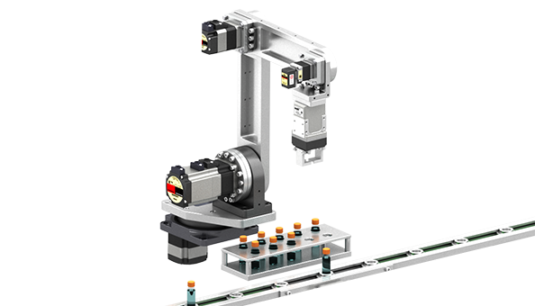
Applications
Table Drive for X-Y Axes

Feeding of Quantitative Dispenser

Vertical Operation of Stocker

Application of Fixed Amount

Motor Types
Stepper motors come in several different types including the standard type, electromagnetic brake type and various geared types. You can choose a type suited to the function and performance required in your application. Typical examples are introduced below.
Standard Type
This is an easy-to-use basic model.
Motors are available in a variety of sizes.

High-Torque Type
High-torque and high response are achieved by inserting a permanent magnet between the small teeth of the rotor and stator. Compared to the standard type of the same size, the torque is significantly increased.

High-Resolution Type
This motor's basic resolution is double that of the standard type.
This results in high positioning accuracy and reduced vibration.

Encoder Type
Monitoring the current position and detecting positional errors are possible.
For example, comparing the command position and current position enables you to check the normal operation of the motor.

Electromagnetic Brake Type
This product incorporates a power off activated type electromagnetic brake.
When there is a blackout or another unexpected event, the electromagnetic brake holds the load in position to prevent it from dropping.
- Once the power is cut off, the self-holding force of the motor is lost and the motor can no longer be held at the stop position in vertical operations or when an external force is applied. In elevating equipment and similar applications, use an electromagnetic brake type.

Geared Type
These motors incorporate a dedicated position control gearhead with reduced backlash to make the most of the high controllability of the motors.
The gearhead ensures high accuracy, smooth operation even in applications where a large load torque is received.

Advantages of geared motors
Oriental Motor offers geared motors, which have been pre-assembled with gearheads, as variations of stepper motors. Using geared motors bring many advantages, such as deceleration, high torque and high resolution, as well as those listed below.
The Motor Can Drive a Large Load Inertia
When a geared motor is used, the load inertia that can be turned increases in proportion to the square of the gear ratio in comparison with a comparable standard motor. This means that larger load inertia can be driven with geared motors.

|

|
|
| Motor Type | Geared Type (Gear ratio 5) | Standard Type |
|---|---|---|
| Product Name | AZM66AC-PS5 | AZM66AC |
| Permissible Load Inertia (30 times the rotor inertia) |
277.5 × 10⁻⁴ kg·m2 | 11.1 × 10⁻⁴ kg·m2 |
| Load Inertia Diameter (Thickness 20 mm, aluminum material) |
317 mm | 142 mm |
| Speed Range | 0-600 r/min | 0~6000 r/min |
Damping characteristics at start and stop can be improved
If the load inertia is large or acceleration/deceleration time is short, a geared motor can decrease damping more effectively and thereby ensure more stable operation compared to a standard motor. Geared motors are ideal for such applications where large inertia as an index table or arm drive must be positioned quickly.


Can be Miniaturized
Compared with a standard motor that generates equivalent maximum holding torque, a geared motor has a smaller frame size, thus its mass and volume can be reduced. Geared motors are effective when the equipment must be made compact and lightweight.

High Rigidity and Torsion-Resistant
Geared motors have high rigidity, so they are resistant to torsion and are less affected by load torque fluctuations than standard motors. This means that stability and high precision positioning can be ensured even if the load size changes.
-
Application: Elevator
High accuracy stopping is possible in mechanisms that operate vertically like elevators, even in situations where the number or weight of loads changes.
-
Application: Surveillance Cameras
The camera can maintain a stable position even when shaken by strong wind.
Direct Mounting of Load is Possible (Harmonic geared type, HPG geared type)
Harmonic geared type (except for frame size 90 mm) and HPG geared type can mount the load directly on the rotating surface integrated with the shaft.
Appearance and Mounting Example

Application: Index Table
This not only reduces the number of parts and processes, but also improves reliability. They are also suitable for operation with moment loads.

Types and Features of Geared Motors
Various types of geared motors are available for stepper motors.
You can select the optimal type based on torque, accuracy (backlash), and more.
Click the figure on the right to refer to the features and main specifications of each type.
- Refer to this to understand the differences between each type.
- The applicable geared motor is different for each Series.

| Gearhead Types | Parallel Shaft | Right-Angle Shaft | |||||||||
|---|---|---|---|---|---|---|---|---|---|---|---|
| SH (Spur gear mechanism) |
CS (Spur gear mechanism) |
TH (Spur gear mechanism) |
TS (Spur gear mechanism) |
PS (Planetary gear mechanism) |
PN (Planetary Gear Mechanism) |
HPG (Harmonic Planetary® |
Harmonic (Harmonic Drive ® |
FC (Face gear mechanism) |
|||
| External View |

|

|

|

|

|

|

|

|

|

|
|
| Features | |||||||||||
| Accuracy | For 2-phase | Low Backlash | Non-Backlash | Low Backlash | |||||||
| ★ | ★ | ★★ | ★★ | ★★ | ★★★ | ★★★ | ★★★ | ★★ | |||
| High Torque | ★ | ★★ | ★ | ★★ | ★★ | ★★ | ★★ | ★★ | ★★ | ||
| Maximum Instantaneous Torque Available | - | - | - | ○ | ○ | ○ | ○ | ○ | - | ||
| Load Face Mounting | - | - | - | - | - | - | - | ○ | ○ | - | |
| Center shaft | - | ○ | - | - | ○ | ○ | ○ | - | ○ | ○ | |
| Main Specifications | |||||||||||
| Types of Gear Ratios | 3.6, 7.2, 9, 10, 18, 36 | 5, 10, 15, 20 | 3.6, 7.2, 10, 20, 30 | 3.6, 7.2, 10, 20, 30 | 5, 7.2, 10, 25, 36, 50 | 5, 7.2, 10, 25, 36, 50 | 5, 15 | 50, 100 | 7.2, 10, 20, 30 | ||
| Speed Range [r/min] | ~833 | ~600 | ~500 | ~833 | ~600 | ~600 | ~900 | ~70 | ~416 | ||
| Permissible Torque [N·m] | ~4 | ~4.5 | ~4 | ~6 | ~8 | ~8 | ~9 | ~10 | ~10.5 | ||
| Maximum Instantaneous Torque [N·m] | - | - | - | ~10 | ~20 | ~20 | ~19 | ~36 | - | ||
| Backlash [arcmin] | 45~70 | 45~70 | 10~35 | 10~35 | 7~9 | 2~3 | 3 | 0 | 10~15 | ||
| Gearhead Types | SH | CS | TH | TS | PS | PN | HPG | Harmonic | FC | ||
- *Refer to the values above to understand the differences between each type. It varies depending on the frame size dimensions and gear ratio.
- *The values in the main specifications are based on a frame size of 60 mm.
- *Harmonic Planetary®, Harmonic Drive®, and HD" are registered trademarks or trademarks of Harmonic Drive Systems Inc.

-
Refer to the technical reference for more information about the principle and structure of each type.
Gearheads for Stepper Motors and Servo Motors
Driver Types
Built-In Controller Type
With this type, operation data is set in the driver, then selected and executed from the host system. Host system connection and control are performed any of the following: I/O, Modbus (RTU)/RS-485 communication, or industrial network. By using a network converter (sold separately), EtherCAT communication are possible.
- FLEX is the collective name for products that support I/O control, Modbus (RTU) control, and industrial network control via network converters.


Pulse Input Type With RS-485 Communication (AZ Series only)
Operation is executed according to the pulse signal input to the driver. The motor is controlled from a positioning module (pulse generator) provided by the customer. RS-485 communication can be used to monitor status information for the motor (position, speed, torque, alarms, temperature, etc.).


Pulse Input Type
Operation is executed according to the pulse signal input to the driver. Motor control is performed from a positioning module (pulse generator) provided by the customer. The support software (MEXE02) can be used to check the alarm history and monitor status information.


Network Compatible Driver (AZ Series only)
This driver supports EtherNet/IP and EtherCAT communications. It can be controlled directly from the network. A single communication cable is used to connect the driver to the host control device, thus saving wiring.

Multi-Axis Driver (AZ Series, DC input only)
This is a multi-axis driver compatible with SSCNETIII/H, MECHATROLINK-III, and EtherCAT.
This driver can be connected to AZ Series DC input motors and electric actuators equipped with such motors.
Drivers with 2-axis, 3-axis and 4-axis connectivity are available.

- *EtherCAT® is registered trademark and patented technology, licensed by Beckhoff Automation GmbH, Germany.
- *EtherNet/IP™ is a trademark of ODVA.
- *Modbus (RTU) is a registered trademark of Schneider Automation Inc.
- *The support software MEXE02 can be downloaded here.
Related Information
For Those Who Have Not Decided on a Series
View More About the Selection Guide
Selection Guide
This selection guide will help you find the product series best suited for your equipment. Select an equipment application example and follow the guidance to select a product series.
Learn More
View More about the Problem Solving Case Studies

Problem Solving Case Studies
Here is the information on the solutions for your equipment issues. We introduce examples of in-house production of equipment used in actual manufacturing sites, as well as application examples of our recommended products to solve the issues with conventional equipment.
Learn More