Gearhead/Linear Head: Gearheads for Stepper Motors and Servo Motors
Since stepper motor and servo motor gearheads are for applications requiring high precision positioning, they are designed with emphasis on high accuracy, high permissible torque, and high speed rotation (for servo motors).
Accordingly, Oriental Motor has developed a mechanism to minimize backlash in gearheads used with stepper motors and servo motors in order to ensure low backlash properties.
Generally, a stepper motor is associated with a larger output torque compared to an AC motor with the same frame size, and servo motors rotate at high speeds. Accordingly, gearheads for stepper motors and servo motors support high torque and high speed so these motor characteristics are not lost.
The basic principles and structures of typical control motor gearheads are explained below.
CS Gearhead
Principle and Structure
TheCS gearhead is a parallel shaft gear reduction mechanism and is a product with the output shaft arranged in the center of the frame size.
A salient is provided on 1 side of the gear case to provide space for the gears to be placed, allowing the center shaft to be mounted flexibly. In addition, by optimizing the design using the salient, we were able to achieve larger diameter gears and bearings. This allows us to increase the permissible torque, permissible radial load, and permissible axial load of the product.
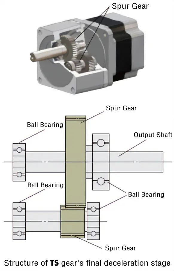
TS Gearhead
Principle and Structure
Through the use of high accuracy gear processing and heat treatment to reduce dimensional variation,TS gearheads reduce their effects on backlash. In addition, because the gear on the output shaft undergoes a high accuracy finishing process after the heat treatment, there are no dimensional variation effects from the heat treatment.
Because of this, TS gearheads allow for simple structures that do not require a special adjustment mechanism.
TH Gearhead
Principle and Structure
InTH gearheads, tapered gears are used in the final stage of the spur gear and the meshing gear. The tapered gear is produced through continuous profile shifting toward the shaft. These tapered gears are fine-tuned to each other to reduce backlash.
FC Gearhead
Principle and Structure
FC gearheads are right-angle shaft-type gearheads that consist of a face gear (disk-shaped gear) and a spur gear. Oriental Motor has succeeded in making the face gear smaller and stronger through our unique high accuracy machining, and have achieved a small right-angle shaft with minimal backlash.
PS Gearhead
Principle and Structure
PS gearheads employ a planetary gear mechanism. The planetary gear mechanism is comprised of 3 key parts: a sun gear, planetary gears and an internal gear. The sun gear is installed on the central axis (in a single stage type, this is the motor shaft) surrounded by multiple planetary gears, and revolves around the central axis via an internal gear. The revolution of planetary gears is translated into rotation of the output shaft via carriers.
- Sun Gear
- A gear located in the center, functioning as an input shaft.
- Planetary Gear
- Several external gears revolving around the sun gear.
Each planetary gear is attached to the carrier, onto which the gearhead output shaft is fixed.
- Internal Gear
- A cylindrical gear affixed to the gear case, having teeth on its inside diameter.
High Permissible Torque
In a conventional spur gear mechanism, the strength of a single gear determines the torque that can be transmitted because the gears contact 1-to-1. However, a planetary gear mechanism can transmit a large amount of torque because the torque is distributed and transmitted by multiple planetary gears.
The torque applied to a single gear in a planetary gear mechanism is as follows.
$${T}= {k}\ \frac{T'}{n}$$
- T
- Torque applied to a single planetary gear [N·m]
- T'
- Torque to be transmitted in total [N·m]
- n
- Number of planetary gears
- k
- Dispersion coefficient
The dispersion coefficient indicates how evenly the torque is dispersed among the individual planetary gears. The closer this value is to 1, the more evenly the torque is dispersed and the greater the amount of torque that can be transferred. In order for the transmission torque to be distributed evenly, the positional relationship of each component must be precisely arranged.
PN Gearhead
Principle and Structure
PN gearheads employs a planetary gear mechanism just like the PS gearhead. The PN gearhead achieves the specified backlash of less than 3 arcmin through the improved finishing accuracy of its components and the backlash eliminator. The backlash eliminator is comprised of 2 sets of internal and planetary gears on the upper and lower levels with the internal gear teeth twisted in the circumferential direction. The upper level internal gears and planetary gears reduce backlash in the CW direction, and the lower level internal gears and planetary gears reduce backlash in the CCW direction. The scissors gear system is applied to achieve non-backlash in a low gear ratio.
High Permissible Torque
ThePN gearheads use the same planetary gear mechanism as the PS gearheads, which allows multiple gears to distribute and transmit torque, resulting in high permissible torque. For details, refer to the "High Permissible Torque" section of PS Gearhead.
Angular Transmission Accuracy
Angular transmission accuracy is the difference between the theoretical rotation angle of the output shaft, as calculated from the input pulse count, and the actual rotation angle. Represented as the difference between the min. value and max. value in the set of measurements taken for a single rotation of the output shaft, starting from an arbitrary position.
Angular Transmission Accuracy by Frame Size
| Frame Size [mm] |
Angular Transmission Accuracy [arcmin] |
|---|---|
| 28, 42 | 6 (0.1˚) |
| 60 | 5 (0.09˚) |
| 90 | 4 (0.07˚) |
HPG Gearhead
Principle and Structure
This is a planetary gear reducer that applies thin elastic gear technology to the internal gears of a planetary gear reducer. By using the elastic deformation of the internal gear, low backlash is achieved without an adjustment mechanism.
Planetary gear reducers have a structure in which the sun gear and planetary gear, and the planetary gear and internal gear mesh simultaneously. Therefore, if the backlash is reduced only by the dimensional accuracy of the parts, the interlocking parts will interfere with each other due to the dimensional error, resulting in uneven rotational torque and noise.
In order to solve these problems, a "thin elastic internal gear" was developed to mitigate interference in the meshing area and provide sufficient strength, resulting in Harmonic Planetary®, the planetary gear reducer with a revolutionary structure. Harmonic Planetary® has almost no backlash change over the lifetime of the reducer.
(Copyright © 1999 HARMONIC DRIVE SYSTEMS INC. All Rights Reserved.)
- Harmonic Planetary® is a registered trademark of Harmonic Drive Systems Inc.
Angular Transmission Accuracy
Angular transmission accuracy is the difference between the theoretical rotation angle of the output shaft, as calculated from the input pulse count, and the actual rotation angle. Represented as the difference between the min. value and max. value in the set of measurements taken for a single rotation of the output shaft, starting from an arbitrary position.
Angular Transmission Accuracy by Frame Size
| Frame Size [mm] |
Angular Transmission Accuracy [arcmin] |
|---|---|
| 40 | 5 (0.09˚) |
| 60 | 4 (0.07˚) |
| 90 | 4 (0.07˚) |
Harmonic gearhead
Principle and Structure
The harmonic gearhead offers excellent precision in positioning for a reducer and features a simple construction that utilizes the metal's elastodynamic property and one comprising of just 3 basic components (wave generator, flex spline and circular spline).
Wave Generator
The wave generator is an oval-shaped component with a thin ball bearing placed around the outer circumference of the oval cam. The bearing's inner ring is fixed to the oval cam, while the outer ring is subjected to elastic deformation via the balls. The wave generator is installed onto the motor shaft.
Flex Spline
The flex spline is a thin, cup-shaped component made of elastic metal. There are teeth formed along the outer circumference of the cup's opening. The gearhead output shaft is attached at the bottom of the flex spline.
Circular Spline
The circular spline is a rigid internal gear. There are teeth formed along its inner circumference. These teeth are the same size as those of the flex spline, but the circular spline has 2 more teeth than the flex spline. The circular spline is fixed to the gear case along its outer circumference.
Combines 3 basic parts. The flex spline is bent into an oval shape by the wave generator. The teeth on the long axis of the oval mesh with the circular spline, while the teeth on the short axis of the oval are completely separate from it.
Rotating the wave generator (input) clockwise while keeping the circular spline fixed in position will subject the flex spline to elastic deformation, causing a gradual shift in the point of engagement between the circular spline and flex spline.
When the wave generator completes a revolution, the flex spline has 2 fewer teeth than the circular spline has, resulting in the movement of flex spline for the difference in the number of teeth (2 teeth) in the opposite direction of the wave generator's rotation (i.e., counterclockwise). This movement translates into output, thereby decelerating the speed.
Accuracy
Unlike the conventional spur gear gearhead, the harmonic gearhead has no backlash. The harmonic gearhead has many teeth in simultaneous meshing engagement, and is designed to average out the effects of tooth pitch error and cumulative pitch error on rotation accuracy to ensure high positioning accuracy. Also, harmonic gearheads have high gear ratio, so that the torsion when the load torque is applied to the output shaft is much smaller than a single motor and other geared motor, and the rigidity is high. High rigidity is less subject to load fluctuation and enables stable positioning. When the high positioning accuracy and rigidity are required, refer to the following characteristics.
Angular Transmission Accuracy
Angular transmission accuracy is the difference between the theoretical rotation angle of the output shaft, as calculated from the input pulse count, and the actual rotation angle. Represented as the difference between the min. value and max. value in the set of measurements taken for a single rotation of the output shaft, starting from an arbitrary position.
| Product Name | Angular Transmission Accuracy [arcmin] |
|---|---|
| AZM24-HS□, ARM24-H□ PKP242-H□ |
2 (0.034˚) |
| AZM46-HS□, ARM46-H□ PKE543-HS□ |
1.5 (0.025˚) |
| AZM66-HS□, ARM66-H□ PKE564-HS□, PKP262-H□S |
|
| AZM98-HS□, ARM98-H□ PKE596-HS |
1 (0.017˚) |
These are the values under no load conditions (gearhead reference value). In actual applications, there is always frictional load, and displacement is produced as a result of this frictional load. If the frictional load is constant, the displacement will be constant for unidirectional operation. However, in bi-directional operation, double the displacement is produced over a round trip. This displacement can be estimated from the following torque – torsion characteristics.
Torque - Torsion Characteristics
The torque – torsion characteristics in the graph measure displacement (torsion) when the motor shaft is fixed and the load (torque) is gradually increased and decreased in the forward and reverse directions of the output shaft. When a load is applied to the output shaft in this way, displacement occurs due to the gear’s spring constant.
This displacement occurs when an external force is applied as the gear is stopped, or when the gear is driven under a frictional load. The slope can be approximated with the spring constant in the following 3 classes, depending on the size of the load torque, and can be estimated through calculation.
1. Load torque \({T_L}\) is \({T_1}\) max.
2. Load torque \({T_L}\) exceeds \({T_1}\) but is less than \({T_2}\)
3. Load torque \({T_L}\) exceeds \({T_2}\)
The torsion angle determined by the calculation is for the harmonic gearhead alone.
Values used for calculation
| Product name\Item | Gear Ratio | T 1
N·m |
K 1
N·m/min |
θ 1
min |
T 2
N·m |
K 2
N·m/min |
θ 2
min |
K 3
N·m/min |
|---|---|---|---|---|---|---|---|---|
|
AZM24-HS50 ARM24-H50 |
50 | 0.29 | 0.08 | 3.7 | − | 0.12 | − | − |
|
AZM24-HS100 ARM24-H100 |
100 | 0.29 | 0.1 | 2.9 | 1.5 | 0.15 | 11 | 0.21 |
|
AZM46-HS50 ARM46-H50 PKE543-HS50 |
50 | 0.8 | 0.64 | 1.25 | 2 | 0.87 | 2.6 | 0.93 |
| PKP242-H50 | 0.29 | 0.13 | 2.3 | 0.75 | 0.19 | 4.5 | 0.24 | |
|
AZM46-HS100 ARM46-H100 PKE543-HS100 |
100 | 0.8 | 0.79 | 1.02 | 2 | 0.99 | 2.2 | 1.28 |
| PKP242-H100 | 0.29 | 0.26 | 1.1 | 0.75 | 0.29 | 2.8 | 0.35 | |
|
AZM66-HS50 ARM66-H50 PKE564-HS50 |
50 | 2 | 0.99 | 2 | 6.9 | 1.37 | 5.6 | 1.66 |
| PKP262-H50S | 0.8 | 0.64 | 1.2 | 2 | 0.87 | 2.8 | 0.93 | |
|
AZM66-HS100 ARM66-H100 PKE564-HS100 |
100 | 2 | 1.37 | 1.46 | 6.9 | 1.77 | 4.2 | 2.1 |
| PKP262-H100S | 0.8 | 0.79 | 1 | 2 | 0.99 | 2.1 | 1.28 | |
|
AZM98-HS50 ARM98-H50 PKE596-HS50 |
50 | 7 | 3.8 | 1.85 | 25 | 5.2 | 5.3 | 6.7 |
|
AZM98-HS100 ARM98-H100 PKE596-HS100 |
100 | 7 | 4.7 | 1.5 | 25 | 7.3 | 4 | 8.4 |
Hysteresis Loss
As shown in the torque – torsion characteristics, the torsion angle will not become 0 and a slight torsion remains even when the torque is removed after applying up to the permissible torque bidirectionally. (Figure B-B')
This is referred to as a hysteresis loss. The harmonic gearhead is designed to have a hysteresis loss of 2 arcmin or less.
When the external force is applied during stopping, or when the acceleration/deceleration torque is applied in the inertial drive, or when the frictional load is applied while driving, etc., a slight torsion remains because of the hysteresis loss, even if there is no load.
Lost Motion
Since the harmonic gearhead has no backlash, lost motion is used as a reference for gear accuracy.
Lost motion represents the total displacement that occurs when a torque corresponding to approximately 5 % of the permissible torque is applied to the gearhead output shaft.