Selecting an Electric Linear Slide/Electric Cylinder: Calculation of Load Moment - Electric Cylinder (With shaft guide only) -
Selection Method
The Load Moment
When a load is transported with an electric cylinder (unit equipped with shaft guide only), a load moment affects the shaft guide if the position of the load's center of gravity is offset from the center (fulcrum) of the shaft guide.
The direction of action applies to 3 directions: pitching (MP), yawing (MY), and rolling (MR), depending on the position of the offset.
Even when the selected electric cylinders satisfy the load mass and positioning time requirements, if the center of gravity of the load is offset from the center (fulcrum) of the shaft guide, the run life may decrease as a result of the load moment. Load moment calculations must be completed and whether the conditions are within specification values must be checked. The moment applied under static conditions is the static permissible moment. The moment applied under movement is the dynamic permissible moment, and both must be checked.
Concept of Load Moment Application
When Used in Horizontal Direction or Wall Mounting Direction
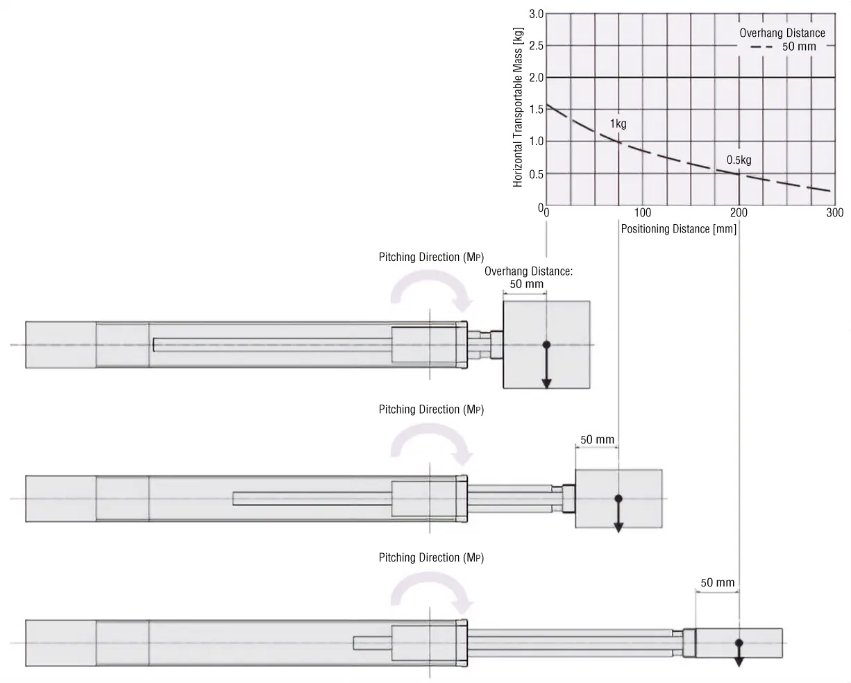
In cases where the load moment acts while the electric cylinder (with shaft guide only) is stopped or operating, check the graph on the product page.
The calculation results are the same for static and dynamic moments.
Permissible Moment in the Pitching Direction (MP)
When installed in the horizontal or wall mounting direction, refer to the Characteristics Diagrams. The Characteristics Diagrams include the calculation results of the load moment not taken into account in the specification table of each product.
Permissible Moment in the Rolling Direction (MR)
When Used in Vertical Direction
Calculate the load moment applied to the electric cylinder (units equipped with shaft guide only) from the load and the direction the load is applied. Check that the static permissible moment and dynamic permissible moment are not exceeded, and check that the strength is sufficient.
- Load Moment Formula:
When there are several overhung loads, etc., it is determined by the sum of moments from all loads.
- For Multiple Loads (n pieces)
Concept of Static Moment Application
The following illustration shows the load moments (ΔMP, ΔMY, and ΔMR) that act when the electric cylinder (units equipped with shaft guide only) is installed and stopped in the vertical direction. Using the formula to determine load moment, check that the load moment is within the range of static permissible moments (MP, MY, MR).
Concept of Dynamic Moment Application
The following illustrations show the load moments (ΔMP, ΔMY, and ΔMR) that act when the electric cylinder (units equipped with shaft guide only) is installed and moving (taking into account acceleration) in the vertical direction. Using the formula to determine load moment, check that the load moment is within the range of dynamic permissible moments (MP, MY, MR).
The expected life distance of the shaft guide part of electric cylinders (equipped with shaft guide) is designed with reference to the life of each series.
However, under conditions where the load moment formula is greater than 1, the expected life distance will be less than the expected value.
Use the formula below to approximate the expected life distance.
- *The expected life varies depending on the product. Refer to here for details.