Q.What is positive grounding, what are the differences from negative grounding, and what precautions should be taken?
Positive grounding is a grounding method in which the positive side of a power supply is connected to the FG (frame ground).
In Japan, negative grounding is usually used, but positive grounding is sometimes used for certain types of equipment.
Comparison of Signal Status When Disconnected by Grounding Method
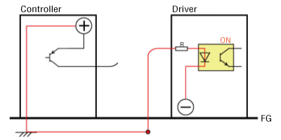
- For negative grounding with sink logic (NPN)
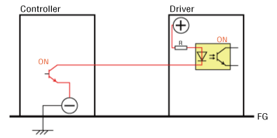
This is a typical connection example using a sink logic controller and driver.
When the transistor on the controller side is turned ON, the photocoupler on the driver side also turns ON, activating the equipment.
Here, we will consider a case where the signal line connecting the controller and the driver is disconnected.
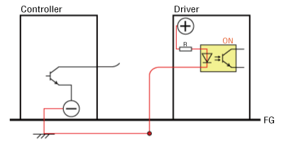
If a broken signal line comes in contact with the casing (FG), a circuit will be formed via the FG.
This circuit does not involve a transistor, making it impossible to turn OFF the photocoupler, which leads to equipment malfunction.
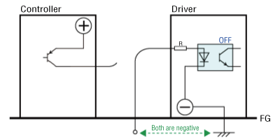
Next, we will consider the case of positive grounding.
- For positive grounding with sink logic (NPN)
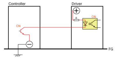
Under normal conditions, the photocoupler turns ON by the same mechanism in negative grounding.
Now, we will consider what happens when the signal line is disconnected, as in the previous case.
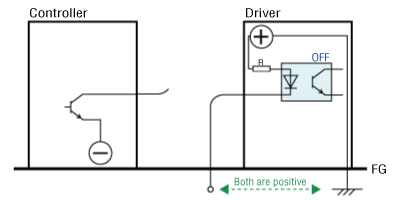
As shown in the figure above, for positive grounding, no electrical current passes even when the broken signal line touches the casing (FG).
This prevents the photocoupler from turning ON, thus preventing equipment malfunction.
- For Source Logic (PNP)
We will also consider situations involving not only sink logic, but source logic as well.
For negative grounding, no electrical current passes even when the broken signal line touches the casing (FG).
Positive grounding may lead to photocoupler malfunction, just like negative grounding using sink logic.
Notes on Positive Grounding
When using positive grounding, make sure all machinery in the equipment (including peripheral equipment) uses positive grounding.
Combining positive grounding and negative grounding is extremely dangerous.
- Risks of Combining Positive and Negative Grounding
Most PCs have an internal 0 V and FG connection. (Negative grounding)
The following figure shows an example of wiring when a PC is connected to a device (controller, driver) with positive grounding.

As shown in the figure, the FG of the PC connects to the FG, connecting their respective power supplies through the FG and causing short-circuiting.
This may damage the controller, driver, or the computer.
Therefore, when using positive grounding, be sure to check that all devices in the equipment are compatible with positive grounding.
Product Category: αSTEP, Stepper Motors, Servo Motors, Electric Actuators
Model and Series: General
Description: Wiring Methods, Technical Knowledge, Materials and Terminology, Setting methods and Installation Methods
FAQ No.: 396
Related FAQs
Email to Technical Support
After opening the email, we will check the contents and contact you. Please note that depending on the nature of your enquiry, we may contact you by phone.