*The following 3 motor shaft types are available in the standard type.
42 mm frame size with key is AZM48 only.
TS Geared Type
AZM1
62
63
A4
C5
-
TS6
7.27
U8
1
Motor Type
AZM
AZ Series Motor
2
Motor Frame Size
4
42 mm
6
60 mm
9
90 mm
3
Motor Case Length
4
Output Shaft Type
A
Single Shaft
M
With Electromagnetic Brake
5
Motor Type
C
AC input specification
6
Geared Type
TS
TS Geared Type
7
Gear Ratio
8
Cable Outlet Direction*
Blank
Down side
U
Upper side
L
Left
R
Right
*The cable outlet direction indicates the direction of the cable, as viewed from the output shaft side with the output shaft at the top of the output shaft face.
FC Geared Type
AZM1
62
63
A4
C5
-
FC6
7.27
U8
A9
1
Motor Type
AZM
AZ Series Motor
2
Motor Frame Size
4
42 mm
6
60 mm
3
Motor Case Length
4
Output Shaft Type
A
Single Shaft
M
With Electromagnetic Brake
5
Motor Type
C
AC input specification
6
Geared Type
FC
FC Geared Type
7
Gear Ratio
8
Cable Outlet Direction*
D
Down side
U
Upper side
9
Classification
A
Solid Shaft
*The cable outlet direction indicates the direction of the cable as viewed from the gearhead side, with the output shaft to the left.
Driver
AZD1
-
C2
D3
1
Driver Type
AZD
AZ Series Driver
2
Power Supply Input
A
Single-Phase 100-120 VAC
C
Single-Phase/Three-Phase 200-240 VAC
3
Product Line
D
Built-in Controller Type
X
Pulse Input Type With RS-485 Communication
Blank
Pulse Input Type
EP
EtherNet/IP Compatible
ED
EtherCAT Compatible
PN
PROFINET Compatible
M3
MECHATROLINK-III Compatible
S3
SSCNET III/H Compatible
Connection Cable Set/Flexible Connection Cable Set
CC1
0502
V3
Z4
F5
B6
1
CC
Cable
2
Length
005
0.5 m
010
1 m
015
1.5 m
020
2 m
025
2.5 m
030
3 m
040
4 m
050
5 m
070
7 m
100
10 m
150
15 m
200
20 m
3
Reference Number
4
Applicable Model
Z
for AZ Series
5
Cable Type
F
Connection Cable Set
R
Flexible Connection Cable Set
6
Description
Blank
For type without electromagnetic brake
B
For Electromagnetic Brake Type
Connector Type (Motor, driver, cable)
Motor
Standard Type
AZM1
62
63
A4
05
C6
H7
PS, Harmonic Geared Type
AZM1
62
63
A4
C6
H7
-
PS8
7.29
1
Motor Type
AZM
AZ Series Motor
2
Motor Frame Size
4
42 mm
6
60 mm
3
Motor Case Length
4
Output Shaft Type
A
Single Shaft
M
With Electromagnetic Brake
5
Additional Functions*
Blank
Single Flat Face
0
Straight Type
1
With key
6
Motor Type
C
AC input specification
7
Motor Connection Method
H
Connector Type
8
Geared Type
PS
PS Geared Type
HP
HPG Geared Type
HS
Harmonic Geared Type
9
Gear Ratio
*The following 3 motor shaft types are available in the standard type.
TS Geared Type
AZM1
62
63
A4
C5
H6
-
TS7
7.28
U9
1
Motor Type
AZM
AZ Series Motor
2
Motor Frame Size
4
42 mm
6
60 mm
9
90 mm
3
Motor Case Length
4
Output Shaft Type
A
Single Shaft
M
With Electromagnetic Brake
5
Motor Type
C
AC input specification
6
Motor Connection Method
H
Connector Type
7
Geared Type
TS
TS Geared Type
8
Gear Ratio
9
Connector Direction*
Blank
Down side
U
Upper side
L
Left
R
Right
*The connector direction indicates the direction as seen from the output shaft side with the output shaft facing up.
FC Geared Type
AZM1
62
63
A4
C5
H6
-
FC7
7.28
U9
A10
1
Motor Type
AZM
AZ Series Motor
2
Motor Frame Size
4
42 mm
6
60 mm
3
Motor Case Length
4
Output Shaft Type
A
Single Shaft
M
With Electromagnetic Brake
5
Motor Type
C
AC input specification
6
Motor Connection Method
H
Connector Type
7
Geared Type
FC
FC Geared Type
8
Gear Ratio
9
Connector Direction*
D
Down side
U
Upper side
10
Classification
A
Solid Shaft
*The connector direction indicates the direction as seen from the gearhead side with the output shaft facing left.
Driver
AZD1
-
C2
D3
1
Driver Type
AZD
AZ Series Driver
2
Power Supply Input
A
Single-Phase 100-120 VAC
C
Single-Phase/Three-Phase 200-240 VAC
3
Product Line
D
Built-in Controller Type
X
Pulse Input Type With RS-485 Communication
Blank
Pulse Input Type
EP
EtherNet/IP Compatible
ED
EtherCAT Compatible
PN
PROFINET Compatible
M3
MECHATROLINK-III Compatible
S3
SSCNET III/H Compatible
Connection Cable/Flexible Connection Cable
CCM1
0102
Z13
A4
F5
F6
1
CCM
Cable
2
Length
010
1 m
020
2 m
030
3 m
050
5 m
070
7 m
100
10 m
3
Applicable Model
Z1
for AZ Series Connector Type
4
Description
A
AC input without electromagnetic brake
B
AC input with electromagnetic brake
5
Cable Outlet Direction*
F
Output Shaft Side
V
Vertical
B
Rear Shaft Side
6
Cable Type
F
Connection Cable Set
R
Flexible Connection Cable Set
*3 types of the connection cables with different outlet directions are available. Select the cable outlet direction, taking into account the installation requirements.
The following 3 motor shaft types are available in the standard type.
Frame sizes of 20 mm and 28 mm are for single flat face only
42 mm frame size with key is AZM48 only.
*2
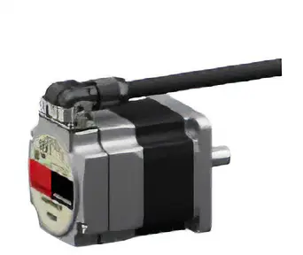
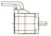
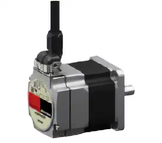
Horizontal outlet direction products have the following motor cable configuration.
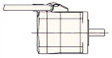
Horizontal Outlet Direction Product
Conventional Product
TS Geared Type
AZM1
62
63
A4
K5
-
TS6
7.27
U8
1
Motor Type
AZM
AZ Series Motor
2
Motor Frame Size
4
42 mm
6
60 mm
3
Motor Case Length
4
Output Shaft Type
A
Single Shaft
M
With Electromagnetic Brake
5
Motor Type
K
DC input specification
6
Geared Type
TS
TS Geared Type
7
Gear Ratio
8
Cable Outlet Direction*
Blank
Down side
U
Upper side
L
Left
R
Right
*The cable outlet direction indicates the direction of the cable, as viewed from the output shaft side with the output shaft at the top of the output shaft face.
FC Geared Type
AZM1
62
63
A4
K5
-
FC6
7.27
U8
A9
1
Motor Type
AZM
AZ Series Motor
2
Motor Frame Size
2
35 mm
4
42 mm
6
60 mm
3
Motor Case Length
4
Output Shaft Type
A
Single Shaft
M
With Electromagnetic Brake
5
Motor Type
K
DC input specification
6
Geared Type
FC
FC Geared Type
7
Gear Ratio
8
Cable Outlet Direction*
D
Down side
U
Upper side
9
Classification
A
Solid Shaft
*The cable outlet direction indicates the direction of the cable as viewed from the gearhead side, with the output shaft to the left.
Driver
AZD1
-
K2
D3
1
Driver Type
AZD
AZ Series Driver
2
Power Supply Input
K
24 VDC/48 VDC
3
Product Line
D
Built-in Controller Type
X
Pulse Input Type With RS-485 Communication
Blank
Pulse Input Type
EP
EtherNet/IP Compatible
ED
EtherCAT Compatible
PN
PROFINET Compatible
Connection Cable Set/Flexible Connection Cable Set
CC1
0502
V3
Z4
5
F6
B7
28
1
CC
Cable
2
Length
005
0.5 m
010
1 m
015
1.5 m
020
2 m
025
2.5 m
030
3 m
040
4 m
050
5 m
070
7 m
100
10 m
150
15 m
200
20 m
3
Reference Number
4
Applicable Model
Z
for AZ Series
5
Reference Number
Blank
For frame size 42 mm (HPG geared type is 40 mm), 60 mm
2
For frame size 20 mm, 28 mm (Harmonic geared type is 30 mm)
6
Cable Type
F
Connection Cable Set
R
Flexible Connection Cable Set
7
Description
Blank
For type without electromagnetic brake
B
For Electromagnetic Brake Type
8
Cable Specification
2
For DC Input
Connector Type (Motor, driver, cable)
Motor
Standard Type
AZM1
62
63
A4
05
K6
H7
PS, Harmonic Geared Type
AZM1
62
63
A4
K6
H7
-
PS8
7.29
1
Motor Type
AZM
AZ Series Motor
2
Motor Frame Size
4
42 mm
6
60 mm
3
Motor Case Length
4
Output Shaft Type
A
Single Shaft
M
With Electromagnetic Brake
5
Additional Functions*
Blank
Single Flat Face
0
Straight Type
1
With key
6
Motor Type
K
DC input specification
7
Motor Connection Method
H
Connector Type
8
Geared Type
PS
PS Geared Type
HP
HPG Geared Type
HS
Harmonic Geared Type
9
Gear Ratio
*The following 3 motor shaft types are available in the standard type.
TS Geared Type
AZM1
62
63
A4
K5
H6
-
TS7
7.28
U9
1
Motor Type
AZM
AZ Series Motor
2
Motor Frame Size
4
42 mm
6
60 mm
9
90 mm
3
Motor Case Length
4
Output Shaft Type
A
Single Shaft
M
With Electromagnetic Brake
5
Motor Type
K
DC input specification
6
Motor Connection Method
H
Connector Type
7
Geared Type
TS
TS Geared Type
8
Gear Ratio
9
Connector Direction*
Blank
Down side
U
Upper side
L
Left
R
Right
*The connector direction indicates the direction as seen from the output shaft side with the output shaft facing up.
FC Geared Type
AZM1
62
63
A4
K5
H6
-
FC7
7.28
U9
A10
1
Motor Type
AZM
AZ Series Motor
2
Motor Frame Size
4
42 mm
6
60 mm
3
Motor Case Length
4
Output Shaft Type
A
Single Shaft
M
With Electromagnetic Brake
5
Motor Type
K
DC input specification
6
Motor Connection Method
H
Connector Type
7
Geared Type
FC
FC Geared Type
8
Gear Ratio
9
Connector Direction*
D
Down side
U
Upper side
10
Classification
A
Solid Shaft
*The connector direction indicates the direction as seen from the gearhead side with the output shaft facing left.
Driver
AZD1
-
K2
D3
1
Driver Type
AZD
AZ Series Driver
2
Power Supply Input
K
24 VDC/48 VDC
3
Product Line
D
Built-in Controller Type
X
Pulse Input Type With RS-485 Communication
Blank
Pulse Input Type
EP
EtherNet/IP Compatible
ED
EtherCAT Compatible
PN
PROFINET Compatible
Connection Cable/Flexible Connection Cable
CCM1
0102
Z13
C4
F5
F6
1
CCM
Cable
2
Length
010
1 m
020
2 m
030
3 m
050
5 m
070
7 m
100
10 m
3
Applicable Model
Z1
for AZ Series Connector Type
4
Description
C
DC input without electromagnetic brake
D
DC input for electromagnetic brake
5
Cable Outlet Direction*
F
Output Shaft Side
V
Vertical
B
Rear Shaft Side
6
Cable Type
F
Connection Cable Set
R
Flexible Connection Cable Set
*3 types of the connection cables with different outlet directions are available. Select the cable outlet direction, taking into account the installation requirements.